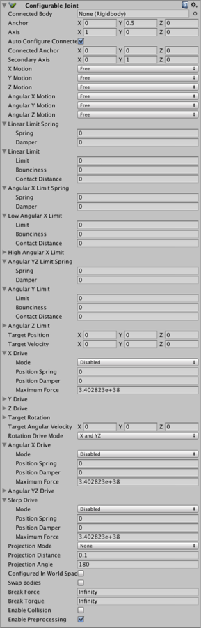
Configurable Joint
Los Configurable Joints son extremamente personalizados. Estos exponen todas las propiedades de Physx relacionadas a las articulaciones, para que sean todas capaces de crear comportamientos similares a todos los otros tipos de articulaciones.
Propiedades
| Propiedad: | Función: |
|---|---|
| Connected Body | The other Rigidbody object to which the joint is connected. You can set this to None to indicate that the joint is attached to a fixed position in space rather than another Rigidbody. |
| Anchor | El punto dónde el centro de la articulación está definida. Toda la simulación basada en la física utilizará este punto como el centro de los cálculos. |
| Axis | El eje local que definirá la rotación natural del objeto basado en la simulación de física. |
| Auto Configure Connected Anchor | Si esto está activado, entonces la posición de Connected Ancho (de conexión de anclaje) será calculada automáticamente para que cuadre con la posición global de la propiedad de anclaje. Este es el comportamiento predeterminado. Si eso está desactivada, usted puede configurar la posición del anclaje conectado manualmente. |
| Connected Anchor | Configuración manual de la posición conectada por anclaje. |
| Secondary Axis | Juntos, el Axis y Secondary Axis definen el sistema de coordenadas local de la articulación. El tercer eje está configurado para ser ortogonal a los otros dos. |
| X, Y, Z Motion | Permite movimiento a lo largo del eje Z en ser Free, Completely Locked, o Limited de acuerdo a Linear Limit |
| Angular X, Y, Z Motion | Permite rotación alrededor del eje Z en ser Free, Completely Locked, o Limited de acuerdo al Angular ZLimit |
| Linear Limit Spring | A spring force applied to pull the object back when it goes past the limit position. |
| Spring | The spring force. If this value is set to zero then the limit will be impassable; a value other than zero will make the limit elastic. |
| Damper | The reduction of the spring force in proportion to the speed of the joint’s movement. Setting a value above zero allows the joint to “dampen” oscillations which would otherwise carry on indefinitely. |
| Linear Limit | El borde definiendo la restricción de movimiento, basado en la distancia desde el origine de la articulación. |
| Limit | La distancia en unidades desde el origen a la pared del limite. |
| Bounciness | La cantidad de fuerza devuelta del rebote aplicada al objeto cuando alcanza el Limit |
| Contact Distance | The minimum distance tolerance (between the joint position and the limit) at which the limit will be enforced. A high tolerance makes the limit less likely to be violated when the object is moving fast. However, this will also require the limit to be taken into account by the physics simulation more often and this will tend to reduce performance slightly. |
| Angular X Limit Spring | A spring torque applied to rotate the object back when it goes past the limit angle of the joint. |
| Spring | The spring torque. If this value is set to zero then the limit will be impassable; a value other than zero will make the limit elastic. |
| Damper | The reduction of the spring torque in proportion to the speed of the joint’s rotation. Setting a value above zero allows the joint to “dampen” oscillations which would otherwise carry on indefinitely. |
| Low Angular X Limit | Lower limit on the joint’s rotation around the X axis, specified as a angle from the joint’s original rotation. |
| Limit | El ángulo límite. |
| Bounciness | Cantidad de torque de rebote devuelto aplicado al objeto cuando su rotación alcanza el Limit |
| Contact Distance | The minimum angular tolerance (between the joint angle and the limit) at which the limit will be enforced. A high tolerance makes the limit less likely to be violated when the object is moving fast. However, this will also require the limit to be taken into account by the physics simulation more often and this will tend to reduce performance slightly. |
| High Angular XLimit | This is similar to the Low Angular X Limit property described above but it determines the upper angular limit of the joint’s rotation rather than the lower limit. |
| Angular YZ Limit Spring | This is similar to the Angular X Limit Spring described above but applies to rotation around both the Y and Z axes. |
| Angular Y Limit | Analogous to the Angular X Limit properties described above but applies to the Y axis and regards both the upper and lower angular limits as being the same. |
| Angular Z Limit | Analogous to the Angular X Limit properties described above but applies to the Z axis and regards both the upper and lower angular limits as being the same. |
| Target Position | La posición deseada a la cual la articulación se debería mover |
| Target Velocity | La velocidad deseada a la cual la articulación se debería mover |
| XDrive | Definición de cómo los movimiento de la articulación se comportarán a lo largo del eje X local. |
| Mode | Configure las siguientes propiedades en ser dependientes en Target Position, Target Velocity, o ambas. |
| Position Spring | The spring force that moves the joint towards its target position. This is only used when the drive mode is set to Position or Position and Velocity. |
| Position Damper | The reduction of the spring force in proportion to the speed of the joint’s movement. Setting a value above zero allows the joint to “dampen” oscillations which would otherwise carry on indefinitely. This is only used when the drive mode is set to Position or Position and Velocity. |
| Maximum Force | The force used to accelerate the joint toward its target velocity. This is only used when the drive mode is set to Velocity or Position and Velocity. |
| YDrive | This is analogous to the X Drive described above but applies to the joint’s Y axis. |
| ZDrive | This is analogous to the X Drive described above but applies to the joint’s Z axis. |
| Target Rotation | The orientation that the joint’s rotational drive should rotate towards, specified as a quaternion. |
| Target Angular Velocity | The angular velocity that the joint’s rotational drive should aim to achieve. This is specified as a vector whose length specifies the rotational speed and whose direction defines the axis of rotation. |
| Rotation Drive Mode | The way in which the drive force will be applied to the object to rotate it to the target orientation. If the mode is set to X and YZ, the torque will be applied around these axes as specified by the Angular X/YZ Drive properties described below. If Slerp mode is used then the Slerp Drive properties will determine the drive torque. |
| Angular X Drive | This specifies how the joint will be rotated by the drive torque around its local X axis. It is used only if the Rotation Drive Mode property described above is set to X & YZ. |
| Mode | Configure las siguientes propiedades en ser dependientes en Target Position, Target Velocity, o ambas. |
| Position Spring | The spring torque that rotates the joint towards its target position. This is only used when the drive mode is set to Position or Position and Velocity. |
| Position Damper | The reduction of the spring torque in proportion to the speed of the joint’s movement. Setting a value above zero allows the joint to “dampen” oscillations which would otherwise carry on indefinitely. This is only used when the drive mode is set to Position or Position and Velocity. |
| Maximum Force | The torque used to accelerate the joint toward its target velocity. This is only used when the drive mode is set to Velocity or Position and Velocity. |
| Angular YZDrive | This is analogous to the Angular X Drive described above but applies to both the joint’s Y and Z axes. |
| Slerp Drive | This specifies how the joint will be rotated by the drive torque around all local axes. It is used only if the Rotation Drive Mode property described above is set to Slerp. |
| Mode | Configure las siguientes propiedades en ser dependientes en Target Position, Target Velocity, o ambas. |
| Position Spring | The spring torque that rotates the joint towards its target position. This is only used when the drive mode is set to Position or Position and Velocity. |
| Position Damper | The reduction of the spring torque in proportion to the speed of the joint’s movement. Setting a value above zero allows the joint to “dampen” oscillations which would otherwise carry on indefinitely. This is only used when the drive mode is set to Position or Position and Velocity. |
| Maximum Force | The torque used to accelerate the joint toward its target velocity. This is only used when the drive mode is set to Velocity or Position and Velocity. |
| Projection Mode | This defines how the joint will be snapped back to its constraints when it unexpectedly moves beyond them (due to the physics engine being unable to reconcile the current combination of forces within the simulation). The options are None and Position and Rotation. |
| Projection Distance | The distance the joint must move beyond its constraints before the physics engine will attempt to snap it back to an acceptable position. |
| Projection Angle | The angle the joint must rotate beyond its constraints before the physics engine will attempt to snap it back to an acceptable position. |
| Configured in World Space | Si está activado, todo los valores deseados serán calculados en el espacio del mundo en vez del espacio local del objeto. |
| Swap Bodies | If enabled, this will make the joint behave as though the component were attached to the connected Rigidbody (ie, the other end of the joint). |
| Break Force | If the joint is pushed beyond its constraints by a force larger than this value then the joint will be permanently “broken” and deleted. |
| Break Torque | If the joint is rotated beyond its constraints by a torque larger than this value then the joint will be permanently “broken” and deleted. |
| Enable Collision | Should the object with the joint be able to collide with the connected object (as opposed to just passing through each other)? |
| Enable Preprocessing | If preprocessing is disabled then certain “impossible” configurations of the joint will be kept more stable rather than drifting wildly out of control. |
Detalles
Like the other joints, the Configurable Joint allows you to restrict the movement of an object but also to drive it to a target velocity or position using forces. However, there are many configuration options available and they can be quite subtle when used in combination; you may need to experiment with different options to get the joint to behave exactly the way you want.
Constraining Movement
You can constrain both translational movement and rotation on each axis independently using the X, Y, Z Motion and X, Y, Z Rotation properties. If Configured In World Space is enabled then movements will be constrained to the world axes rather than the object’s local axes. Each of these properties can be set to Locked, Limited or Free:
- A Locked axis will allow no movement at all. For example, an object locked in the world Y axis cannot move up or down.
- A Limited axis allows free movement between predefined limits, as explained below. For example, a gun turret might be given a restricted arc of fire by limiting its Y rotation to a specific angular range.
- A Free axis allows any movement.
You can limit translational movement using the Linear Limit property, which defines the maximum distance the joint can move from its point of origin. (measured along each axis separately). For example, you could constrain the puck for an air hockey table by locking the joint in the Y axis (in world space), leaving it free in the Z axis and setting the limit for the X axis to fit the width of the table; the puck would then be constrained to stay within the playing area.

You can also limit rotation using the Angular Limit properties. Unlike the linear limit, these allow you to specify different limit values for each axis. Additionally, you can also define separate upper and lower limits on the angle of rotation for the X axis (the other two axes use the same angle either side of the original rotation). For example, you could construct a “teeter table” using a flat plane with a joint constrained to allow slight tilting in the X and Z directions while leaving the Y rotation locked.
Bounciness and Springs
By default, a joint simply stops moving when it runs into its limit. However, an inelastic collision like this is rare in the real world and so it is useful to add some feeling of bounce to a constrained joint. You can use the Bounciness property of the linear and angular limits to make the constrained object bounce back after it hits its limit. Most collisions will look more natural with a small amount of bounciness but you can also set this property higher to simulate unusually bouncy boundaries like, say, the cushions of a pool table.

The joint limits can be softened further using the spring properties: Linear Limit Spring for translation and Angular X/YZ Limit Spring for rotation. If you set the Spring property to a value above zero, the joint will not abruptly stop moving when it hits a limit but will be drawn back to the limit position by a spring force (the strength of the force is determined by the Spring value). By default, the spring is perfectly elastic and will tend to catapult the joint back in the direction opposite to the collision. However, you can use the Damper property to reduce the elasticity and return the joint to the limit more gently. For example, you might use a spring joint to create a lever that can be pulled to the left or right but then springs back to an upright position. If the springs are perfectly elastic then the lever will tend to oscillate back and forth around the centre point after it is released. However, if you add enough damping then the spring will rapidly settle down to the neutral position.

Drive forces
Not only can a joint react to the movements of the attached object, but it can also actively apply drive forces to set the object in motion. Some joints simple need to keep the object moving at a constant speed as with, say, a rotary motor turning a fan blade. You can set your desired velocity for such joints using the Target Velocity and Target Angluar Velocity properties. You might also require joints that move their object towards a particular position in space (or a particular orientation); you can set these using the Target Position and Target Rotation properties. For example, you could implement a forklift by mounting the forks on a configurable joint and then setting the target height to raise them from a script.
With the target set, the X, Y, Z Drive and Angular X/YZ Drive (or alternatively Slerp Drive) properties then specify the force used to push the joint toward it. The Drives’ Mode property selects whether the joint should seek a target position, velocity or both. The Position Spring and Position Damper work in the same way as for the joint limits when seeking a target position. In velocity mode, the spring force is dependent on the “distance” between the current velocity and the target velocity; the damper helps the velocity to settle at the chosen value rather than oscillating endlessly around it. The Maximum Force property is a final refinement that prevents the force applied by the spring from exceeding a limit value regardless of how far the joint is from its target. This prevents the circumstance where a joint stretched far from its target rapidly snaps the object back in an uncontrolled way.
Note that with all the drive forces (except for Slerp Drive, described below), the force is applied separately in each axis. So, for example, you could implement a spacecraft that has a high forward flying speed but a relatively low speed in sideways steering motion.
Slerp Drive
While the other drive modes apply forces in separate axes, Slerp Drive uses the Quaternion’s spherical interpolation or “slerp” functionality to reorient the joint. Rather than isolating individual axes, the slerp process essentially finds the minimum total rotation that will take the object from the current orientation to the target and applies it on all axes as necessary. Slerp drive is slightly easier to configure and fine for most purposes but does not allow you to specify different drive forces for the X and Y/Z axes.
To enable Slerp drive, you should change the Rotation Drive Mode property from X and YZ to Slerp. Note that the modes are mutually exclusive; the joint will use either the Angular X/YZ Drive values or the Slerp Drive values but not both together.