Emission
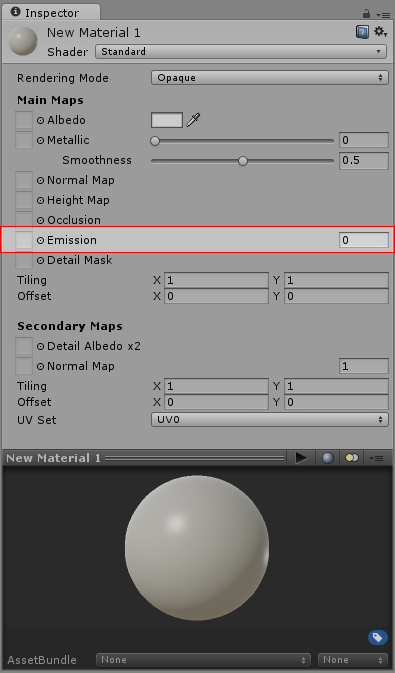
Controls colour and intensity of light emitted from the surface. When an emissive material is used in your scene, it appears to be a visible source of light itself. The object will appear “self illuminated”.
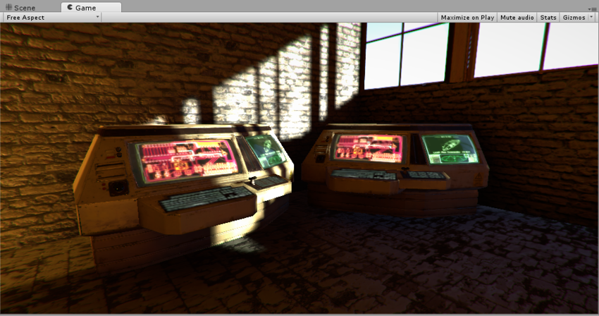
Emissive materials are usually used on objects where some part should appear to be lit up from inside, such as the screen of a monitor, the disc brakes of a car braking at high speed, glowing buttons on a control panel, or a monster’s eyes which are visible in the dark.
Simple emissive materials can be defined using a single colour and emission level. If you set the emission level to a value higher than the default zero, the emission colour and strength field will appear:
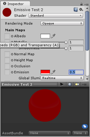
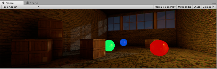
Objects using these materials will appear to remain bright even when in dark areas in your scene.
As well as simple control over emission using a flat colour and brightness setting, you can assign an emission map to this parameter. As with the other texture map parameters, this gives you much finer control over which areas of your material appear to emit light.
If a texture map is assigned, the full colour values of the texture are used for the emission colour and brightness. The emission value numeric field remains, which you can use as a multiplier to boost or reduce the overall emission level of your material.
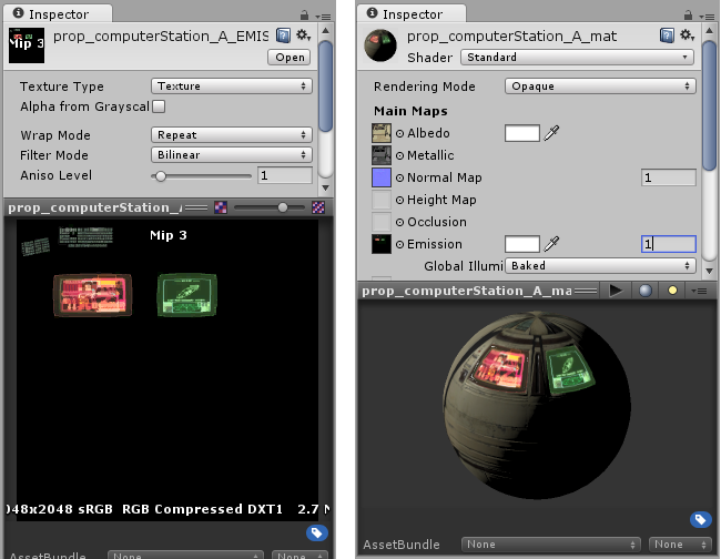
As well as the emission colour and brightness, the Emission parameter has a Global Illumination setting, allowing you to specify how the apparent light emitted from this material will affect the contextual lighting of other nearby objects. There are three options
None - The object will appear emissive, but the lighting of nearby objects will not be affected.
Realtime - The emissive light from this material will be added to the realtime global illumination calculations for the scene, so the lighting of nearby objects, even moving objects, will be affected by the emitted light.
Baked - The emissive light from this material will be baked into the static lightmaps for the scene, so other nearby static objects will appear to be lit by this material, but dynamic objects will not be affected.
