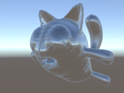
ビルトインレンダーパイプラインでの法線マップテクスチャシェーダーの例
__法線マップ__は多くの場合、追加のジオメトリを作成せずに、オブジェクトに追加の詳細を作成するために使用されます。法線マップテクスチャを使用して環境を反射するシェーダーの作成法を見てみましょう。
計算がかなり複雑になってきたので、何段階かに分けて行いたいと思います。前述のシェーダーでは、リフレクションの方向は、頂点シェーダーの頂点ごとに計算され、フラグメントシェーダーはリフレクションプローブのキューブマップを参照するだけでした。ただし、法線マップを使い始めると、表面の法線自体を各ピクセルごとに計算することが必要になります。つまり、ピクセルごとに周囲の反射を計算しなくてはいけないということです。
ここでは新しく学ぶことも必要になります。いわゆる “接空間” です。法線マップテクスチャは、ほとんどの場合、モデルの “表面に沿っている” と考えられる座標空間で表現されます。シェーダーでは、接空間の基底ベクトルを知り、テクスチャから法線ベクトルを読み取り、ワールド空間に変換してから、上記のシェーダーからすべての計算を行う必要があります。やってみましょう。
Shader "Unlit/SkyReflection Per Pixel"
{
    Properties {
        // normal map texture on the material,
        // default to dummy "flat surface" normalmap
        _BumpMap("Normal Map", 2D) = "bump" {}
    }
    SubShader
    {
        Pass
        {
            CGPROGRAM
            #pragma vertex vert
            #pragma fragment frag
            #include "UnityCG.cginc"

            struct v2f {
                float3 worldPos : TEXCOORD0;
                // these three vectors will hold a 3x3 rotation matrix
                // that transforms from tangent to world space
                half3 tspace0 : TEXCOORD1; // tangent.x, bitangent.x, normal.x
                half3 tspace1 : TEXCOORD2; // tangent.y, bitangent.y, normal.y
                half3 tspace2 : TEXCOORD3; // tangent.z, bitangent.z, normal.z
                // texture coordinate for the normal map
                float2 uv : TEXCOORD4;
                float4 pos : SV_POSITION;
            };

            // vertex shader now also needs a per-vertex tangent vector.
            // in Unity tangents are 4D vectors, with the .w component used to
            // indicate direction of the bitangent vector.
            // we also need the texture coordinate.
            v2f vert (float4 vertex : POSITION, float3 normal : NORMAL, float4 tangent : TANGENT, float2 uv : TEXCOORD0)
            {
                v2f o;
                o.pos = UnityObjectToClipPos(vertex);
                o.worldPos = mul(_Object2World, vertex).xyz;
                half3 wNormal = UnityObjectToWorldNormal(normal);
                half3 wTangent = UnityObjectToWorldDir(tangent.xyz);
                // compute bitangent from cross product of normal and tangent
                half tangentSign = tangent.w * unity_WorldTransformParams.w;
                half3 wBitangent = cross(wNormal, wTangent) * tangentSign;
                // output the tangent space matrix
                o.tspace0 = half3(wTangent.x, wBitangent.x, wNormal.x);
                o.tspace1 = half3(wTangent.y, wBitangent.y, wNormal.y);
                o.tspace2 = half3(wTangent.z, wBitangent.z, wNormal.z);
                o.uv = uv;
                return o;
            }

            // normal map texture from shader properties
            sampler2D _BumpMap;

            fixed4 frag (v2f i) : SV_Target
            {
                // sample the normal map, and decode from the Unity encoding
                half3 tnormal = UnpackNormal(tex2D(_BumpMap, i.uv));
                // transform normal from tangent to world space
                half3 worldNormal;
                worldNormal.x = dot(i.tspace0, tnormal);
                worldNormal.y = dot(i.tspace1, tnormal);
                worldNormal.z = dot(i.tspace2, tnormal);

                // rest the same as in previous shader
                half3 worldViewDir = normalize(UnityWorldSpaceViewDir(i.worldPos));
                half3 worldRefl = reflect(-worldViewDir, worldNormal);
                half4 skyData = UNITY_SAMPLE_TEXCUBE(unity_SpecCube0, worldRefl);
                half3 skyColor = DecodeHDR (skyData, unity_SpecCube0_HDR);
                fixed4 c = 0;
                c.rgb = skyColor;
                return c;
            }
            ENDCG
        }
    }
}
非常に難解でしたが、見てください。反射に法線マップが適用されています。