頂点とフラグメントシェーダーの例
ここでは、頂点とフラグメントシェーダーの例をさらに詳しく説明します。 シェーダーの基本的な説明は、ShaderLab と固定関数シェーダーと頂点とフラグメントプログラムを参照してください。 標準マテリアルシェーダーを書く簡単な方法は、Surface Shader の記述を参照してください。
(以下のリンクから、例をダウンロードすることができます。Unity プロジェクトの Zip ファイルはこちら)
シーンの設定
もし、Unity のシーンビュー、ヒエラルキービュー、 プロジェクトビュー、インスペクターに慣れていなければ、 Unity 入門からはじまるマニュアルの最初の数セクションを、是非、読んでみてください。
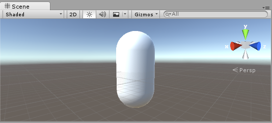
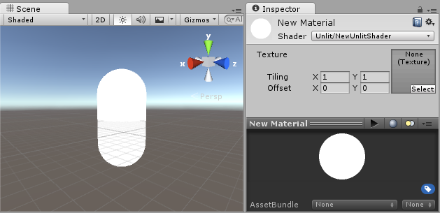
まず最初に、シェーダーのテストに使うオブジェクトを作成します。メインメニューから Game Object > 3D Object > Capsule を選択してください。カメラを配置すると、カプセルがあるのが見えます。 Hierarchy 上でカプセルをダブルクリックすると シーンビュー上でカプセルがフォーカスされるので、メインのカメラを選択して、メインメニューから Game object > Align with View をクリックしてください。
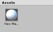
プロジェクトウインドウのメニューから Create > Material を選択して新規の マテリアル を作成します。新規マテリアルは New Material と命名され、プロジェクトビュー上に出現します。
シェーダーの作成
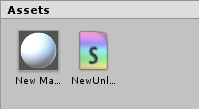
続いて、同様に新しいシェーダーアセットを作成します。プロジェクトウインドウのメニューから Create > Shader > Unlit Shader を選択します。 これにより、まったくライティングされていないテクスチャを表示するだけの、必要最小限のシェーダーが作成されます。
Create > Shader メニューでは、この他に必要最小限のシェーダーや 他のタイプのシェーダー、例えば基本的なサーフェスシェーダーを作成できます。
メッシュ、マテリアル、シェーダーのリンク
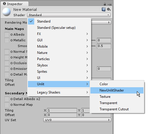
プロジェクトビュー上でシェーダーアセットをマテリアルアセットにドラッグするか、インスペクターを使って マテリアル にシェーダーを割り当てます。このシェーダーが適用されると、マテリアルインスペクター上に白い球が表示されます。
次に、マテリアルをシーンビューかヒエラルキービュー上で、メッシュオブジェクトにドラッグします。または、オブジェクトを選択し Mesh Renderer コンポーネントのマテリアルスロットから、マテリアルを割り当てる事もできます。
これらのセットアップによって、シェーダーコードを見る事ができるようになるので、シェーダーに変更を加えると、結果をシーンビュー上のカプセルで確認できるようになります。
シェーダーの主要な部品
シェーダーコードの分析を始めるには、プロジェクトウインドウでシェーダーアセットをダブルクリックします。すると、シェーダーコードがスクリプトウインドウで開きます (MonoDevelop または Visual Studio) 。
以下のように表示されます。
シェーダーはこのコードで始まります。
Shader "Unlit/NewUnlitShader"
{
    Properties
    {
        _MainTex ("Texture", 2D) = "white" {}
    }
    SubShader
    {
        Tags { "RenderType"="Opaque" }
        LOD 100

        Pass
        {
            CGPROGRAM
            #pragma vertex vert
            #pragma fragment frag
            // make fog work
            #pragma multi_compile_fog

            #include "UnityCG.cginc"

            struct appdata
            {
                float4 vertex : POSITION;
                float2 uv : TEXCOORD0;
            };

            struct v2f
            {
                float2 uv : TEXCOORD0;
                UNITY_FOG_COORDS(1)
                float4 vertex : SV_POSITION;
            };

            sampler2D _MainTex;
            float4 _MainTex_ST;

            v2f vert (appdata v)
            {
                v2f o;
                o.vertex = mul(UNITY_MATRIX_MVP, v.vertex);
                o.uv = TRANSFORM_TEX(v.uv, _MainTex);
                UNITY_TRANSFER_FOG(o,o.vertex);
                return o;
            }

            fixed4 frag (v2f i) : SV_Target
            {
                // sample the texture
                fixed4 col = tex2D(_MainTex, i.uv);
                // apply fog
                UNITY_APPLY_FOG(i.fogCoord, col);
                return col;
            }
            ENDCG
        }
    }
}
この最初のシェーダーはあまり簡単には見えませんが、心配いりません。 それぞれの部分を順に説明してゆきます。
この基本的なシェーダーの主要部分を見てみましょう。
Shader
スラッシュ “/” を使用すると、シェーダーはマテリアルインスペクターのサブメニューに表示されます。
Properties
マテリアルの一部として保存されマテリアルインスペクターに表示される、 シェーダー変数 (テクスチャ、色など) が含まれています。 Unlit シェーダーテンプレートでは、1つのテクスチャプロパティーが宣言されています。
SubShader
サブシェーダーは主に、シェーダーを異なる GPU 能力に合わせて実装するために使用されます。 ここでは、サブシェーダーについてはあまり触れないので、 例にあるすべてのシェーダーには 1つしかサブシェーダーがありません。
Pass
それぞれのパスはシェーダーのマテリアルを伴ってレンダリングされた同じオブジェクトの頂点、および、フラグメントコードの実行を意味しています。
多くの簡易なシェーダーは、1つのパスしか必要ありませんが、 ライティングに関するシェーダーは複数のパスを必用とする場合があります (詳細は、 Unity のレンダリングパイプラインを参照してください)。 通常、パス内のコマンドは、ブレンディングモードのような固定関数状態を設定します。
CGPROGRAM .. ENDCG
通常、ここがコードの大切な部分です。 詳しくは、頂点シェーダーと Fragment シェーダーのプログラミングを参照してください。
シンプルな Unlit シェーダー
Unlit シェーダーテンプレートは、テクスチャでオブジェクトを表示するために絶対に必要なこと以外に、 さらにいくつかのことを行います。 例えば、フォグのサポートや、マテリアルで Texture の Tiling/Offset フィールドの設定を行います。 シェーダーについては最低限にしておいて、さらに他のコメントを加えます。
Shader "Unlit/SimpleUnlitTexturedShader"
{
    Properties
    {
        // we have removed support for texture tiling/offset,
        // so make them not be displayed in material inspector
        [NoScaleOffset] _MainTex ("Texture", 2D) = "white" {}
    }
    SubShader
    {
        Pass
        {
            CGPROGRAM
            // use "vert" function as the vertex shader
            #pragma vertex vert
            // use "frag" function as the pixel (fragment) shader
            #pragma fragment frag

            // vertex shader inputs
            struct appdata
            {
                float4 vertex : POSITION; // vertex position
                float2 uv : TEXCOORD0; // texture coordinate
            };

            // vertex shader outputs ("vertex to fragment")
            struct v2f
            {
                float2 uv : TEXCOORD0; // texture coordinate
                float4 vertex : SV_POSITION; // clip space position
            };

            // vertex shader
            v2f vert (appdata v)
            {
                v2f o;
                // transform position to clip space
                // (multiply with model*view*projection matrix)
                o.vertex = mul(UNITY_MATRIX_MVP, v.vertex);
                // just pass the texture coordinate
                o.uv = v.uv;
                return o;
            }

            // texture we will sample
            sampler2D _MainTex;

            // pixel shader; returns low precision ("fixed4" type)
            // color ("SV_Target" semantic)
            fixed4 frag (v2f i) : SV_Target
            {
                // sample texture and return it
                fixed4 col = tex2D(_MainTex, i.uv);
                return col;
            }
            ENDCG
        }
    }
}
Vertex Shader は 3D モデルの各頂点を計算するプログラムです。それ以上、特別なことは何もありません。オブジェクトスペースの頂点座標は、 GPU がオブジェクトを画面上にラスタライズするために使われる “clip space” に変換されます。フラグメントシェーダーでテクスチャをサンプリングする必要があるので、入力時のままのテクスチャ座標も渡されます。
Fragment Shader は、画面上に映っているオブジェクトを表す、すべてのピクセルを一つ一つ処理するプログラムで、通常、各ピクセルの色を計算し、出力するのに使われます。一般的に、画面上には百万単位のピクセルが存在していますが、フラグメントシェーダーはそれらすべてで実行されるのです!
フラグメントシェーダーの最適化は、ゲームのパフォーマンス全体に関わる、きわめて重要な部分です。
いくつかの変数や関数定義は : POSITION や : SV_Target のようなセマンティクスを伴います。これらのセマンティクスによって、変数の「意味」が GPU に伝えられます。詳細は、シェーダーセマンティクスを参照してください。
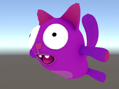
実際、適切なモデルに適切なテクスチャを使用すると、シェーダーが単純であってもなかなかよい感じに見えるものです。
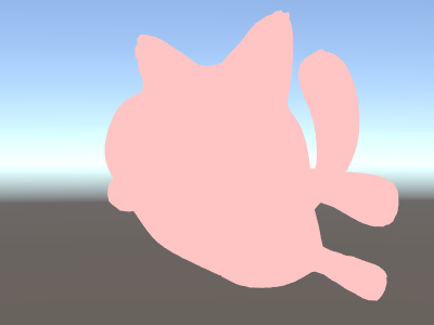
よりシンプルに - 単色シェーダー
シェーダーをよりシンプルにしましょう – すべてのオブジェクトを単色で描画するシェーダーを作成します。 これではまったく役に立たない訳ですが、ここから学習を始めましょう。
Shader "Unlit/SingleColor"
{
    Properties
    {
        // Color property for material inspector, default to white
        _Color ("Main Color", Color) = (1,1,1,1)
    }
    SubShader
    {
        Pass
        {
            CGPROGRAM
            #pragma vertex vert
            #pragma fragment frag

            // vertex shader
            // this time instead of using "appdata" struct, just spell inputs manually,
            // and instead of returning v2f struct, also just return a single output
            // float4 clip position
            float4 vert (float4 vertex : POSITION) : SV_POSITION
            {
                return mul(UNITY_MATRIX_MVP, vertex);
            }

            // color from the material
            fixed4 _Color;

            // pixel shader, no inputs needed
            fixed4 frag () : SV_Target
            {
                return _Color; // just return it
            }
            ENDCG
        }
    }
}
今回は、 (appdata) インプットと (v2f) アウトプットの構造体は使わず、シェーダー関数を手動で書いていきます。どちらの方法でもよいので、あなたのコーディングスタイルと好みで選択してください。
メッシュの法線で楽しく収益用に
前置きはこのぐらいにして、ワールド空間でメッシュの法線を表示するシェーダーから始めます。
Shader "Unlit/WorldSpaceNormals"
{
    // no Properties block this time!
    SubShader
    {
        Pass
        {
            CGPROGRAM
            #pragma vertex vert
            #pragma fragment frag
            // include file that contains UnityObjectToWorldNormal helper function
            #include "UnityCG.cginc"

            struct v2f {
                // we'll output world space normal as one of regular ("texcoord") interpolators
                half3 worldNormal : TEXCOORD0;
                float4 pos : SV_POSITION;
            };

            // vertex shader: takes object space normal as input too
            v2f vert (float4 vertex : POSITION, float3 normal : NORMAL)
            {
                v2f o;
                o.pos = mul(UNITY_MATRIX_MVP, vertex);
                // UnityCG.cginc file contains function to transform
                // normal from object to world space, use that
                o.worldNormal = UnityObjectToWorldNormal(normal);
                return o;
            }

            fixed4 frag (v2f i) : SV_Target
            {
                fixed4 c = 0;
                // normal is a 3D vector with xyz components; in -1..1
                // range. To display it as color, bring the range into 0..1
                // and put into red, green, blue components
                c.rgb = i.worldNormal*0.5+0.5;
                return c;
            }
            ENDCG
        }
    }
}
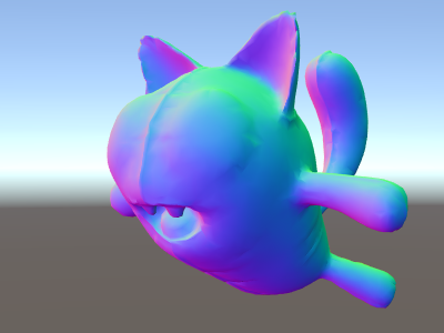
法線は、カラー以外のグラフィックス効果すべてで利用されます – ライティング、反射、輪郭線、その他さまざまな効果などです。
上述してシェーダーでは、 Unity にあらかじめ用意されている shader include files の一つを使う事から始めました。
ここでは、 UnityCG.cginc は UnityObjectToWorldNormal という扱いやすい関数を内包して、使いました。
頂点シェーダーからフラグメントシェーダーには、いわゆる “interpolators” (もしくは “varyings” と呼ばれる事もある) として、データが渡されます。 HLSL シェーディング言語では、一般的に TEXCOORDn セマンティックとしてラべリングされ、それらすべてが 4 成分のベクトルになります (詳細は [semantics]SL-ShaderSemantics ページを参照してください)
すでに法線ベクトルをカラーとして表示する簡単な方法は学んでいるので ( –1.0 から +1.0 の範囲) 、半分は乗算し、半分は加算します。他にも vertex program inputs のページに、頂点データを可視化するサンプルがいろいろあるので、参照してください。
ワールド空間の法線を使用した環境リフレクション
Skybox がリフレクションのソース ( Lighting Window 参照)として使われている場合、 基本的には “デフォルト” の Reflection Probe が作成され、スカイボックスのデータを内包します。 リフレクションプローブは、内部的には Cubemap テクスチャです。参照できるように、上述したワールド空間の法線シェーダーを拡張します。
コードが少し複雑になってきました。もちろん、光と影、反射、その他さまざまなライティングを自動的にシェーダーで機能させたいのであれば、 Surface Shaders を使うという、もっと簡単な方法もあります。このサンプルには、ライティングシステムの各要素を “手動で” 使う方法を教えるという狙いがあるのです。
Shader "Unlit/SkyReflection"
{
    SubShader
    {
        Pass
        {
            CGPROGRAM
            #pragma vertex vert
            #pragma fragment frag
            #include "UnityCG.cginc"

            struct v2f {
                half3 worldRefl : TEXCOORD0;
                float4 pos : SV_POSITION;
            };

            v2f vert (float4 vertex : POSITION, float3 normal : NORMAL)
            {
                v2f o;
                o.pos = mul(UNITY_MATRIX_MVP, vertex);
                // compute world space position of the vertex
                float3 worldPos = mul(_Object2World, vertex).xyz;
                // compute world space view direction
                float3 worldViewDir = normalize(UnityWorldSpaceViewDir(worldPos));
                // world space normal
                float3 worldNormal = UnityObjectToWorldNormal(normal);
                // world space reflection vector
                o.worldRefl = reflect(-worldViewDir, worldNormal);
                return o;
            }

            fixed4 frag (v2f i) : SV_Target
            {
                // sample the default reflection cubemap, using the reflection vector
                half4 skyData = UNITY_SAMPLE_TEXCUBE(unity_SpecCube0, i.worldRefl);
                // decode cubemap data into actual color
                half3 skyColor = DecodeHDR (skyData, unity_SpecCube0_HDR);
                // output it!
                fixed4 c = 0;
                c.rgb = skyColor;
                return c;
            }
            ENDCG
        }
    }
}
上のサンプルでは、用意されている shader include files から、いくらかの要素を利用しています。
-
ビルトインのシェーダー変数 から
unity_SpecCube0、unity_SpecCube0_HDR、_Object2World、UNITY_MATRIX_MVP。 unity_SpecCube0 にはアクティブなリフレクションプローブのデータが含まれます。 -
UNITY_SAMPLE_TEXCUBEビルトインマクロ は、キューブマップをサンプリングするために使用されます。 たいていの標準キューブマップは、標準 HLSL シンタックス (samplerCUBEとtexCUBE) を使用して宣言、および、使用されます。ただし、Unity のリフレクションプローブのキューブマップは、サンプラースロットを節約するために特別な方法で宣言されます。このことを知らなくても、心配することはありません。unity_SpecCube0 キューブマップを使用するには、UNITY_SAMPLE_TEXCUBE マクロを使用しなければならないことだけ、覚えておいてください。 - UnityCG.cginc から
UnityWorldSpaceViewDirとDecodeHDR関数。後者は、リフレクションプローブデータから実際のカラーを取得するのに使用されます。これは、Unity がリフレクションプローブキューブマップを特別にエンコードした方法で保存しているからです。 -
reflectは単なるビルトイン HLSL 関数で、法線周囲のベクトルのリフレクションを計算します。
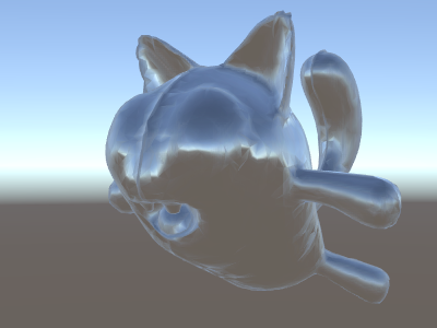
法線マップを使った環境リフレクション
多くの場合 Normal Maps は、ジオメトリを追加せずに、オブジェクトにディティールを追加するために使われます。法線マップテクスチャを使いつつ、周囲の環境を反射するシェーダーの作り方を見ていきます。
計算が かなり複雑に なってきたので、何段階かに分けて行いたいと思います。上述のシェーダーでは、 リフレクションの方向は、 (頂点シェーダー内部で) 頂点ごとに計算され、フラグメントシェーダーはリフレクションプローブのキューブマップをルックアップしているだけでした。 ですが、法線マップを使う場合、面法線自体を各ピクセルごとに計算する必要があり、つまりそれは、ピクセルごとに周囲の環境の反射を計算しなくてはいけないと言う事になるのです !
そのため、まず最初は、いくらかの計算をフラグメントシェーダーに移すように上述のシェーダーを書き直し、ピクセル毎の計算ができるようにします。
Shader "Unlit/SkyReflection Per Pixel"
{
    SubShader
    {
        Pass
        {
            CGPROGRAM
            #pragma vertex vert
            #pragma fragment frag
            #include "UnityCG.cginc"

            struct v2f {
                float3 worldPos : TEXCOORD0;
                half3 worldNormal : TEXCOORD1;
                float4 pos : SV_POSITION;
            };

            v2f vert (float4 vertex : POSITION, float3 normal : NORMAL)
            {
                v2f o;
                o.pos = mul(UNITY_MATRIX_MVP, vertex);
                o.worldPos = mul(_Object2World, vertex).xyz;
                o.worldNormal = UnityObjectToWorldNormal(normal);
                return o;
            }

            fixed4 frag (v2f i) : SV_Target
            {
                // compute view direction and reflection vector
                // per-pixel here
                half3 worldViewDir = normalize(UnityWorldSpaceViewDir(i.worldPos));
                half3 worldRefl = reflect(-worldViewDir, i.worldNormal);

                // same as in previous shader
                half4 skyData = UNITY_SAMPLE_TEXCUBE(unity_SpecCube0, worldRefl);
                half3 skyColor = DecodeHDR (skyData, unity_SpecCube0_HDR);
                fixed4 c = 0;
                c.rgb = skyColor;
                return c;
            }
            ENDCG
        }
    }
}
これだけでは十分ではありません – シェーダーは、モデルの各頂点の代わりに、画面上のすべてのピクセルを計算するようになった分だけ計算量が増えて、実行速度が遅くなった以外は、まったく同じに見えます。ですが、これらの計算は無駄ではありません。多くの場合、高度に写実的なグラフィックスには、より複雑なシェーダーが必要になるのです。
さらに、ここで “ 接空間 ” について理解する必要があります。一般的に、法線マップテクスチャはモデルの “ 表面を覆う ” 座標空間上で表現されます。シェーダーでは、接空間を基準としたベクトルを取得し、テクスチャから法線ベクトルを読み込み、ワールドスペースに変換する必要があります。そしてその後、シェーダーですべての計算を行います。 さあ、やってみましょう !
Shader "Unlit/SkyReflection Per Pixel"
{
    Properties {
        // normal map texture on the material,
        // default to dummy "flat surface" normalmap
        _BumpMap("Normal Map", 2D) = "bump" {}
    }
    SubShader
    {
        Pass
        {
            CGPROGRAM
            #pragma vertex vert
            #pragma fragment frag
            #include "UnityCG.cginc"

            struct v2f {
                float3 worldPos : TEXCOORD0;
                // these three vectors will hold a 3x3 rotation matrix
                // that transforms from tangent to world space
                half3 tspace0 : TEXCOORD1; // tangent.x, bitangent.x, normal.x
                half3 tspace1 : TEXCOORD2; // tangent.y, bitangent.y, normal.y
                half3 tspace2 : TEXCOORD3; // tangent.z, bitangent.z, normal.z
                // texture coordinate for the normal map
                float2 uv : TEXCOORD4;
                float4 pos : SV_POSITION;
            };

            // vertex shader now also needs a per-vertex tangent vector.
            // in Unity tangents are 4D vectors, with the .w component used to
            // indicate direction of the bitangent vector.
            // we also need the texture coordinate.
            v2f vert (float4 vertex : POSITION, float3 normal : NORMAL, float4 tangent : TANGENT, float2 uv : TEXCOORD0)
            {
                v2f o;
                o.pos = mul(UNITY_MATRIX_MVP, vertex);
                o.worldPos = mul(_Object2World, vertex).xyz;
                half3 wNormal = UnityObjectToWorldNormal(normal);
                half3 wTangent = UnityObjectToWorldDir(tangent.xyz);
                // compute bitangent from cross product of normal and tangent
                half tangentSign = tangent.w * unity_WorldTransformParams.w;
                half3 wBitangent = cross(wNormal, wTangent) * tangentSign;
                // output the tangent space matrix
                o.tspace0 = half3(wTangent.x, wBitangent.x, wNormal.x);
                o.tspace1 = half3(wTangent.y, wBitangent.y, wNormal.y);
                o.tspace2 = half3(wTangent.z, wBitangent.z, wNormal.z);
                o.uv = uv;
                return o;
            }

            // normal map texture from shader properties
            sampler2D _BumpMap;

            fixed4 frag (v2f i) : SV_Target
            {
                // sample the normal map, and decode from the Unity encoding
                half3 tnormal = UnpackNormal(tex2D(_BumpMap, i.uv));
                // transform normal from tangent to world space
                half3 worldNormal;
                worldNormal.x = dot(i.tspace0, tnormal);
                worldNormal.y = dot(i.tspace1, tnormal);
                worldNormal.z = dot(i.tspace2, tnormal);

                // rest the same as in previous shader
                half3 worldViewDir = normalize(UnityWorldSpaceViewDir(i.worldPos));
                half3 worldRefl = reflect(-worldViewDir, worldNormal);
                half4 skyData = UNITY_SAMPLE_TEXCUBE(unity_SpecCube0, worldRefl);
                half3 skyColor = DecodeHDR (skyData, unity_SpecCube0_HDR);
                fixed4 c = 0;
                c.rgb = skyColor;
                return c;
            }
            ENDCG
        }
    }
}
やれやれ、非常に難解でした。ですが見てください、反射に法線マップが適用されています !
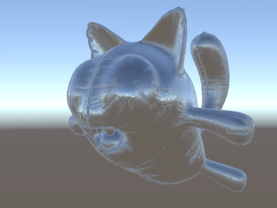
テクスチャの追加
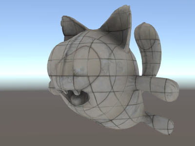
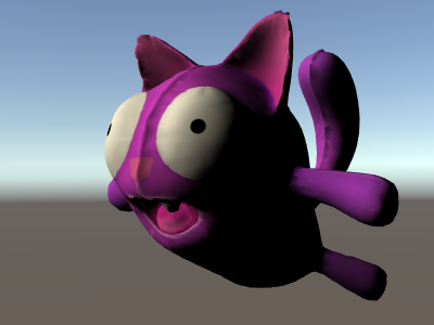
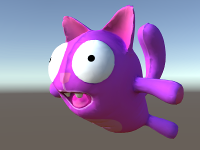
法線マップを加味して空を反射するようになったシェーダーに、さらにテクスチャを追加していきましょう。最初の照明無しのサンプルで用いたベースカラーのテクスチャと、窪みを暗くするためのオクルージョンを追加します。
Shader "Unlit/More Textures"
{
    Properties {
        // three textures we'll use in the material
        _MainTex("Base texture", 2D) = "white" {}
        _OcclusionMap("Occlusion", 2D) = "white" {}
        _BumpMap("Normal Map", 2D) = "bump" {}
    }
    SubShader
    {
        Pass
        {
            CGPROGRAM
            #pragma vertex vert
            #pragma fragment frag
            #include "UnityCG.cginc"

            // exactly the same as in previous shader
            struct v2f {
                float3 worldPos : TEXCOORD0;
                half3 tspace0 : TEXCOORD1;
                half3 tspace1 : TEXCOORD2;
                half3 tspace2 : TEXCOORD3;
                float2 uv : TEXCOORD4;
                float4 pos : SV_POSITION;
            };
            v2f vert (float4 vertex : POSITION, float3 normal : NORMAL, float4 tangent : TANGENT, float2 uv : TEXCOORD0)
            {
                v2f o;
                o.pos = mul(UNITY_MATRIX_MVP, vertex);
                o.worldPos = mul(_Object2World, vertex).xyz;
                half3 wNormal = UnityObjectToWorldNormal(normal);
                half3 wTangent = UnityObjectToWorldDir(tangent.xyz);
                half tangentSign = tangent.w * unity_WorldTransformParams.w;
                half3 wBitangent = cross(wNormal, wTangent) * tangentSign;
                o.tspace0 = half3(wTangent.x, wBitangent.x, wNormal.x);
                o.tspace1 = half3(wTangent.y, wBitangent.y, wNormal.y);
                o.tspace2 = half3(wTangent.z, wBitangent.z, wNormal.z);
                o.uv = uv;
                return o;
            }

            // textures from shader properties
            sampler2D _MainTex;
            sampler2D _OcclusionMap;
            sampler2D _BumpMap;

            fixed4 frag (v2f i) : SV_Target
            {
                // same as from previous shader...
                half3 tnormal = UnpackNormal(tex2D(_BumpMap, i.uv));
                half3 worldNormal;
                worldNormal.x = dot(i.tspace0, tnormal);
                worldNormal.y = dot(i.tspace1, tnormal);
                worldNormal.z = dot(i.tspace2, tnormal);
                half3 worldViewDir = normalize(UnityWorldSpaceViewDir(i.worldPos));
                half3 worldRefl = reflect(-worldViewDir, worldNormal);
                half4 skyData = UNITY_SAMPLE_TEXCUBE(unity_SpecCube0, worldRefl);
                half3 skyColor = DecodeHDR (skyData, unity_SpecCube0_HDR);
                fixed4 c = 0;
                c.rgb = skyColor;

                // modulate sky color with the base texture, and the occlusion map
                fixed3 baseColor = tex2D(_MainTex, i.uv).rgb;
                fixed occlusion = tex2D(_OcclusionMap, i.uv).r;
                c.rgb *= baseColor;
                c.rgb *= occlusion;

                return c;
            }
            ENDCG
        }
    }
}
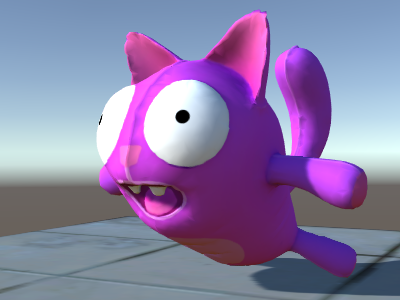
バルーンの猫の見栄えが良くなりました !
テクスチャリングシェーダーの例
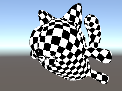
プロシージャルな市松模様
これは、メッシュのテクスチャ座標を基準にして市松模様を出力するシェーダーです:
Shader "Unlit/Checkerboard"
{
    Properties
    {
        _Density ("Density", Range(2,50)) = 30
    }
    SubShader
    {
        Pass
        {
            CGPROGRAM
            #pragma vertex vert
            #pragma fragment frag

            struct v2f
            {
                float2 uv : TEXCOORD0;
                float4 vertex : SV_POSITION;
            };

            float _Density;

            v2f vert (float4 pos : POSITION, float2 uv : TEXCOORD0)
            {
                v2f o;
                o.vertex = mul(UNITY_MATRIX_MVP, pos);
                o.uv = uv * _Density;
                return o;
            }

            fixed4 frag (v2f i) : SV_Target
            {
                float2 c = i.uv;
                c = floor(c) / 2;
                float checker = frac(c.x + c.y) * 2;
                return checker;
            }
            ENDCG
        }
    }
}
Properties 項目にある density のスライダーで市松模様の密度をコントロールします。頂点シェーダーでは、この密度の値によってメッシュの UV座標 0 から 1 の範囲を、 0 から density 値の範囲まで増加します。ここでは density を 30 に設定します - これは、メッシュの様々な場所をレンダリングするために 0 から 30 までの浮動小数点数の値で i.uv をフラグメントシェーダーに入力します。
その後、フラグメントシェーダーのコードは、入力された座標から
HLSL に用意されている floor 関数を使って整数部分だけを取り出し、それを 2 で割ります。入力された座標は 0 から 30 までで有ることを思い出してください ; これによりどんな入力値も 0, 0.5, 1, 1.5, 2, 2.5, などの値に “quantized” されます。この作業は入力された座標の x と y それぞれの成分に行われます。
次に、これらの xy 座標(とり得る値は必ず 0, 0.5, 1, 1.5, 等)を一緒に追加し、 HLSL に用意されているまた別の関数 frac を使って、端数のみを取り出します。結果は、 0.0 か 0.5 のどちらかになります。それからさらに 2 を掛ける事で 0.0 か 1.0 にして、カラー値として出力します (結果は、それぞれ真っ黒か真っ白です) 。
Tri-planar テクスチャ法
プロシージャル、もしくは複雑なメッシュでは、通常の UV 座標を用いたテクスチャ設定の代わりに、オブジェクトに 3 方向からの “project” テクスチャを使った方がやりやすい事があります。これは “tri-planar” テクスチャ法と呼ばれます。面法線を 3 方向からのテクスチャの重み付けに使うという考え方です。シェーダーはこのようになります:
Shader "Unlit/Triplanar"
{
    Properties
    {
        _MainTex ("Texture", 2D) = "white" {}
        _Tiling ("Tiling", Float) = 1.0
        _OcclusionMap("Occlusion", 2D) = "white" {}
    }
    SubShader
    {
        Pass
        {
            CGPROGRAM
            #pragma vertex vert
            #pragma fragment frag

            struct v2f
            {
                half3 objNormal : TEXCOORD0;
                float3 coords : TEXCOORD1;
                float2 uv : TEXCOORD2;
                float4 pos : SV_POSITION;
            };

            float _Tiling;

            v2f vert (float4 pos : POSITION, float3 normal : NORMAL, float2 uv : TEXCOORD0)
            {
                v2f o;
                o.pos = mul(UNITY_MATRIX_MVP, pos);
                o.coords = pos.xyz * _Tiling;
                o.objNormal = normal;
                o.uv = uv;
                return o;
            }

            sampler2D _MainTex;
            sampler2D _OcclusionMap;

            fixed4 frag (v2f i) : SV_Target
            {
                // use absolute value of normal as texture weights
                half3 blend = abs(i.objNormal);
                // make sure the weights sum up to 1 (divide by sum of x+y+z)
                blend /= dot(blend,1.0);
                // read the three texture projections, for x,y,z axes
                fixed4 cx = tex2D(_MainTex, i.coords.yz);
                fixed4 cy = tex2D(_MainTex, i.coords.xz);
                fixed4 cz = tex2D(_MainTex, i.coords.xy);
                // blend the textures based on weights
                fixed4 c = cx * blend.x + cy * blend.y + cz * blend.z;
                // modulate by regular occlusion map
                c *= tex2D(_OcclusionMap, i.uv);
                return c;
            }
            ENDCG
        }
    }
}
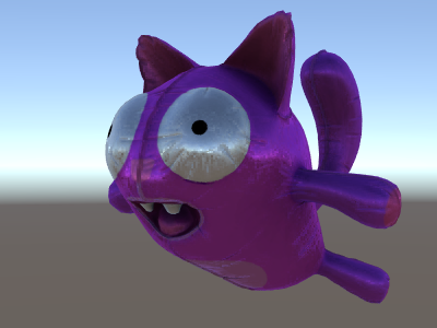
ライティングの計算
一般的に、Unity のライティングパイプラインのためのシェーダーが必要な場合、 サーフェスシェーダー を書きます。 サーフェスシェーダーは、「厄介な分部」のほとんどをかたずけてくれます。実際にシェーダーコードで書かなければならないのは、サーフェスプロパティーの宣言だけです。
ただし、場合によって、標準サーフェスシェーダーパスを避けた方がよい場合があります。 それは、パフォーマンスに関する理由で、全体のライティングパイプラインの限られたサブセットだけをサポートしたい場合か、 または、あまり「標準ライティング」ではないカスタム化したものを実行したい場合、いずれかです。 以下の例で、手動で書いた頂点、およびフラグメントシェーダーからどのようにライティングデータに働きかけるかを説明します。 サーフェスシェーダーによって (シェーダーインスペクター で) 生成されたコードを見ることもまた、 よい学習リソースです。
シンプルな拡散ライティング
最初にやらなくてはいけないのは、シェーダーが実際に必要とするライティング情報を示す事です。 Unity の rendering pipeline は様々なレンダリング方法をサポートしていますが、ここではデフォルトの forward rendering を使います。
まずは平行光源を 1 灯だけ使う事から始めます。 Unity のフォワードレンダリングは、メインの平行光源、アンビエントライト、ライトマップ、それにリフレクションを用いて、 ForwardBase と呼ばれる単一のパスでレンダリングします。シェーダーでは、 pass tag を追加する事でこれを示します :Tags {"LightMode"="ForwardBase"} 。これにより、いくらかの built-in variables によってシェーダーに平行光源が渡されます。
これは、頂点単位の拡散反射光を計算し、テクスチャを 1 枚だけ使う、簡単なシェーダーです:
Shader "Lit/Simple Diffuse"
{
    Properties
    {
        [NoScaleOffset] _MainTex ("Texture", 2D) = "white" {}
    }
    SubShader
    {
        Pass
        {
            // indicate that our pass is the "base" pass in forward
            // rendering pipeline. It gets ambient and main directional
            // light data set up; light direction in _WorldSpaceLightPos0
            // and color in _LightColor0
            Tags {"LightMode"="ForwardBase"}

            CGPROGRAM
            #pragma vertex vert
            #pragma fragment frag
            #include "UnityCG.cginc" // for UnityObjectToWorldNormal
            #include "UnityLightingCommon.cginc" // for _LightColor0

            struct v2f
            {
                float2 uv : TEXCOORD0;
                fixed4 diff : COLOR0; // diffuse lighting color
                float4 vertex : SV_POSITION;
            };

            v2f vert (appdata_base v)
            {
                v2f o;
                o.vertex = mul(UNITY_MATRIX_MVP, v.vertex);
                o.uv = v.texcoord;
                // get vertex normal in world space
                half3 worldNormal = UnityObjectToWorldNormal(v.normal);
                // dot product between normal and light direction for
                // standard diffuse (Lambert) lighting
                half nl = max(0, dot(worldNormal, _WorldSpaceLightPos0.xyz));
                // factor in the light color
                o.diff = nl * _LightColor0;
                return o;
            }

            sampler2D _MainTex;

            fixed4 frag (v2f i) : SV_Target
            {
                // sample texture
                fixed4 col = tex2D(_MainTex, i.uv);
                // multiply by lighting
                col *= i.diff;
                return col;
            }
            ENDCG
        }
    }
}
これによってオブジェクトにライトの方向が反映するようになります - ライト方向に向いている部分が光り、反対を向いている部分は、全く光りません。
アンビエントのディフューズライティング
上記の例ではアンビエントライティングやライトプローブが考慮されていません。修正しましょう !
修正は、たった 1 行コードを追加するだけです。アンビエントと light probe のデータが、球面調和関数でシェーダーに渡され、 UnityCG.cginc include file の ShadeSH9 関数がその全てを評価し、ワールドスペースの法線が与えられます。
Shader "Lit/Diffuse With Ambient"
{
    Properties
    {
        [NoScaleOffset] _MainTex ("Texture", 2D) = "white" {}
    }
    SubShader
    {
        Pass
        {
            Tags {"LightMode"="ForwardBase"}

            CGPROGRAM
            #pragma vertex vert
            #pragma fragment frag
            #include "UnityCG.cginc"
            #include "UnityLightingCommon.cginc"

            struct v2f
            {
                float2 uv : TEXCOORD0;
                fixed4 diff : COLOR0;
                float4 vertex : SV_POSITION;
            };

            v2f vert (appdata_base v)
            {
                v2f o;
                o.vertex = mul(UNITY_MATRIX_MVP, v.vertex);
                o.uv = v.texcoord;
                half3 worldNormal = UnityObjectToWorldNormal(v.normal);
                half nl = max(0, dot(worldNormal, _WorldSpaceLightPos0.xyz));
                o.diff = nl * _LightColor0;

                // the only difference from previous shader:
                // in addition to the diffuse lighting from the main light,
                // add illumination from ambient or light probes
                // ShadeSH9 function from UnityCG.cginc evaluates it,
                // using world space normal
                o.diff.rgb += ShadeSH9(half4(worldNormal,1));
                return o;
            }

            sampler2D _MainTex;

            fixed4 frag (v2f i) : SV_Target
            {
                fixed4 col = tex2D(_MainTex, i.uv);
                col *= i.diff;
                return col;
            }
            ENDCG
        }
    }
}
このシェーダーは実際のところ、用意されている Legacy Diffuse シェーダーにとてもよく似てきました !
シャドウキャスティングの実装
このシェーダーは、まだ影を落とす事も受ける事もできません。シャドウキャスティングを実装しましょう。
影を落とすために、シェーダーの subshaders か fallback に ShadowCaster pass type が必要です。 ShadowCaster のパスは、シャドウマップを使ってオブジェクトをレンダリングしますが、これは非常に単純です。頂点シェーダーには頂点座標の評価しか必要ありませんし、フラグメントシェーダーは、全く何もする必要がありません。シャドウマップはただのデプスバッファであり、そのためフラグメントシェーダーからカラーを出力する必要も有りません。
これは、多くのシェーダーで同様です。シャドウキャスターのパスは大体いつも同じになります (オブジェクトが、カスタムの頂点シェーダーに基づいて変形したり、カットアウトのアルファを使った半透明部分が有ったりする場合を除く)。シェーダーコマンド UsePass で使いまわすのが、最も簡単な方法です。
Pass
{
    // regular lighting pass
}
// pull in shadow caster from VertexLit built-in shader
UsePass "Legacy Shaders/VertexLit/SHADOWCASTER"
ですが、今は学習の途中なので、同じことをいわゆる “手動で” 行いましょう。コードを短くするために、 ライティングのパス (“ForwardBase”) を、テクスチャを使わないアンビエントのみのコードに置き換えました。その下に、オブジェクトがシャドウキャスティングできるようにするための “ShadowCaster” のパスがあります。
Shader "Lit/Shadow Casting"
{
    SubShader
    {
        // very simple lighting pass, that only does non-textured ambient
        Pass
        {
            Tags {"LightMode"="ForwardBase"}
            CGPROGRAM
            #pragma vertex vert
            #pragma fragment frag
            #include "UnityCG.cginc"
            struct v2f
            {
                fixed4 diff : COLOR0;
                float4 vertex : SV_POSITION;
            };
            v2f vert (appdata_base v)
            {
                v2f o;
                o.vertex = mul(UNITY_MATRIX_MVP, v.vertex);
                half3 worldNormal = UnityObjectToWorldNormal(v.normal);
                // only evaluate ambient
                o.diff.rgb = ShadeSH9(half4(worldNormal,1));
                o.diff.a = 1;
                return o;
            }
            fixed4 frag (v2f i) : SV_Target
            {
                return i.diff;
            }
            ENDCG
        }

        // shadow caster rendering pass, implemented manually
        // using macros from UnityCG.cginc
        Pass
        {
            Tags {"LightMode"="ShadowCaster"}

            CGPROGRAM
            #pragma vertex vert
            #pragma fragment frag
            #pragma multi_compile_shadowcaster
            #include "UnityCG.cginc"

            struct v2f {
                V2F_SHADOW_CASTER;
            };

            v2f vert(appdata_base v)
            {
                v2f o;
                TRANSFER_SHADOW_CASTER_NORMALOFFSET(o)
                return o;
            }

            float4 frag(v2f i) : SV_Target
            {
                SHADOW_CASTER_FRAGMENT(i)
            }
            ENDCG
        }
    }
}
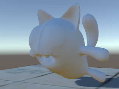
さて、下の方に飛行機があります。標準ビルトイン拡散シェーダーを使用しているので、 シャドウが実行されているのがわかります (現在使用しているシェーダーは、影を_受けることを_まだサポートしていないことを覚えておいてください)。
#pragma multi_compile_shadowcaster ディレクティブを使用します。これによって、シェーダーはそれぞれ定義された異なるプリプロセッサーマクロを持つ数種のバリアントにコンパイルされます
(詳細は、複数のシェーダープログラムのバリアントを作る を参照してください)。シャドウマップにレンダリングするとき、「ポイントライト」対「他のライトタイプ」の場合は、少し違うシェーダーコードが必要です。そのため、このディレクティブが必要です。
受影
影を受けるためのサポートを実装するには、基本ライティングパスを数種のバリアントにコンパイルし、
「影なしのディレクショナルライト」と「影ありのディレクショナルライト」の場合を適切に取り扱う必要があります。
#pragma multi_compile_fwdbase ディレクティブによって、これを実行できます (詳細は、複数のシェーダープログラムのバリアントを作る を参照してください)。実際は、そのディレクティブは、もっとたくさんのことを行います。
リアルタイム GI のオン/オフ、その他、異なるタイプのライトマップ向けのバリアントもコンパイルします。現状、その全てが必要な訳では無いので、それらのバリアントはスキップしてしまって問題ありません。
実際のシャドウイングの計算を取得するために、#include "AutoLight.cginc" のシェーダー includeファイル と SHADOW_COORDS、TRANSFER_SHADOW、SHADOW_ATTENUATION マクロを使用します。
これが、シェーダーです。
Shader "Lit/Diffuse With Shadows"
{
    Properties
    {
        [NoScaleOffset] _MainTex ("Texture", 2D) = "white" {}
    }
    SubShader
    {
        Pass
        {
            Tags {"LightMode"="ForwardBase"}
            CGPROGRAM
            #pragma vertex vert
            #pragma fragment frag
            #include "UnityCG.cginc"
            #include "Lighting.cginc"

            // compile shader into multiple variants, with and without shadows
            // (we don't care about any lightmaps yet, so skip these variants)
            #pragma multi_compile_fwdbase nolightmap nodirlightmap nodynlightmap novertexlight
            // shadow helper functions and macros
            #include "AutoLight.cginc"

            struct v2f
            {
                float2 uv : TEXCOORD0;
                SHADOW_COORDS(1) // put shadows data into TEXCOORD1
                fixed3 diff : COLOR0;
                fixed3 ambient : COLOR1;
                float4 pos : SV_POSITION;
            };
            v2f vert (appdata_base v)
            {
                v2f o;
                o.pos = mul(UNITY_MATRIX_MVP, v.vertex);
                o.uv = v.texcoord;
                half3 worldNormal = UnityObjectToWorldNormal(v.normal);
                half nl = max(0, dot(worldNormal, _WorldSpaceLightPos0.xyz));
                o.diff = nl * _LightColor0.rgb;
                o.ambient = ShadeSH9(half4(worldNormal,1));
                // compute shadows data
                TRANSFER_SHADOW(o)
                return o;
            }

            sampler2D _MainTex;

            fixed4 frag (v2f i) : SV_Target
            {
                fixed4 col = tex2D(_MainTex, i.uv);
                // compute shadow attenuation (1.0 = fully lit, 0.0 = fully shadowed)
                fixed shadow = SHADOW_ATTENUATION(i);
                // darken light's illumination with shadow, keep ambient intact
                fixed3 lighting = i.diff * shadow + i.ambient;
                col.rgb *= lighting;
                return col;
            }
            ENDCG
        }

        // shadow casting support
        UsePass "Legacy Shaders/VertexLit/SHADOWCASTER"
    }
}
見てください、今度は影ができました。
その他のシェーダーの例
霧
Shader "Custom/TextureCoordinates/Fog" {
    SubShader {
        Pass {
            CGPROGRAM
            #pragma vertex vert
            #pragma fragment frag

            //Needed for fog variation to be compiled.
            #pragma multi_compile_fog

            #include "UnityCG.cginc"

            struct vertexInput {
                float4 vertex : POSITION;
                float4 texcoord0 : TEXCOORD0;
            };

            struct fragmentInput{
                float4 position : SV_POSITION;
                float4 texcoord0 : TEXCOORD0;

                //Used to pass fog amount around number should be a free texcoord.
                UNITY_FOG_COORDS(1)
            };

            fragmentInput vert(vertexInput i){
                fragmentInput o;
                o.position = mul (UNITY_MATRIX_MVP, i.vertex);
                o.texcoord0 = i.texcoord0;

                //Compute fog amount from clip space position.
                UNITY_TRANSFER_FOG(o,o.position);
                return o;
            }

            fixed4 frag(fragmentInput i) : SV_Target {
                fixed4 color = fixed4(i.texcoord0.xy,0,0);

                //Apply fog (additive pass are automatically handled)
                UNITY_APPLY_FOG(i.fogCoord, color);

                //to handle custom fog color another option would have been
                //#ifdef UNITY_PASS_FORWARDADD
                //  UNITY_APPLY_FOG_COLOR(i.fogCoord, color, float4(0,0,0,0));
                //#else
                //  fixed4 myCustomColor = fixed4(0,0,1,0);
                //  UNITY_APPLY_FOG_COLOR(i.fogCoord, color, myCustomColor);
                //#endif

                return color;
            }
            ENDCG
        }
    }
}
(上の例をダウンロードすることができます。Unity プロジェクトの Zip ファイルはこちら)
参考文書
- 頂点シェーダーとフラグメントシェーダーのプログラミング.
- Shader Semantics
- Surface Shaders の記述
- シェーダーリファレンス Shader コマンドはシェーダーの名前の文字列を含んでいます。 Properties ブロックには、 シェーダーは、1つ以上のサブシェーダーを持つことが可能です。 各サブシェーダーは、いくつかの パスで構成されています。 このようなキーワードが、頂点やフラグメントシェーダー内で、Cg/HLSL コード部分を囲っています。