Physics Debug Display component reference
Explore the settings to visualize Unity Physics behavior in the Unity Editor and at runtime.
To visualize Unity Physics, add a Physics Debug Display component. When you work with Entities, you must add the component to a subscene.
Physics Debug Display properties
The Physics Debug Display contains the following properties.
Debug Display Options properties
The Debug Display Options contain the following properties.
| Property | Description |
|---|---|
| Draw Colliders | Displays a solid collider around the object. |
| Draw Collider Edges | Displays only the edges of the collider. |
| Draw Collider AABBs | Displays the collider's axis-aligned bounding box (AABB), which the broadphase uses. |
| Draw Mass Properties | Displays the mass properties. |
| Draw Broadphase | Displays the broadphase expansion of the bodies' collider AABBs caused by collision detection between two bodies. Draw Collider AABBs doesn't show this expansion. |
| Draw Contacts | Displays a visualization of all contacts. |
| Draw Collision Events | Displays a visualization of all collision events. |
| Draw Trigger Events | Displays a visualization of all trigger events. |
| Draw Joints | Displays a visualization of all joints, with degrees of freedom, constraints, anchor points, and axis alignments. |
Constraint Graph properties
The Constraint Graph contains the following properties.
| Property | Description |
|---|---|
| Draw Direct Solver Islands | Displays the joints and contacts that the Direct Solver resolves, as lines between the connected rigid bodies' centers. Each line color corresponds to a separate subproblem (a so-called island) that the solver resolves individually and in parallel (in a multithreaded simulation). |
| Draw Iterative Solver Phases | Displays the joints and contacts that the Iterative Solver resolves, as lines between the connected rigid bodies' centers. Each line color corresponds to a subset of joints and contacts (a phase) that the solver might resolve in parallel (in a multithreaded simulation). The iterative solver display also includes joints and contacts that the direct solver resolves, because both solvers process these elements. |
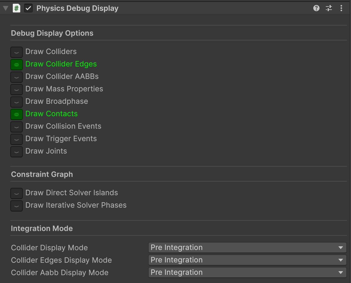
Physics Debug Display component.
Integration Mode properties
Integration Mode contains the following properties.
| Property | Description |
|---|---|
| Collider Display Mode | Displays the debug display mode for colliders. |
| Collider Edges Display Mode | Displays the debug display mode for collider edges. |
| Collider Aabb Display Mode | Displays the debug display mode for the colliders' axis-aligned boundary boxes. |
The debug display has two modes for the Collider, Collider Edges, and the Collider AABBs displays:
- Pre Integration: The colliders display based on their positions and orientations before the physics step, as Unity Physics saw them in the collision detection stage of the current physics step.
- Post Integration: The colliders display based on their position and orientation after the physics step, as they appear after Unity Physics has updated their positions and orientations at the end of the current physics step.