Generate 2D visual content
You use the Mesh API or Vector API to generate 2D visual content onto a visual element.
You can use the Mesh API to draws custom shapes. The Mesh API is a tool for advanced users. If you only want to generate simple geometry, use the Vector API instead. Inspired by HTML Canvas, the Vector API draws 2D vector graphics, such as lines, arcs, and shapes.
Use the Mesh API
To use the Mesh API, allocate a mesh with the MeshGenerationContext.Allocate method and then fill the vertices and indices. The MeshGenerationContext.Allocate method allocates and draws the specified number of vertices and indices required to express geometry for drawing the content of a visual element. For details on geometry generation conventions, see Vertex.position.
The following code snippet generates a single quad. It allocates vertices and indices, and provides coordinates in a clockwise direction:
class QuadMeshElement : VisualElement
{
    public Color color = Color.red;

    public QuadMeshElement()
    {
        generateVisualContent += OnGenerateVisualContent;
    }

    void OnGenerateVisualContent(MeshGenerationContext mgc)
    {
        var mesh = mgc.Allocate(4, 6);

        var p0 = Vector2.zero;
        var p1 = new Vector2(layout.width, 0);
        var p2 = new Vector2(layout.width, layout.height);
        var p3 = new Vector2(0, layout.height);

        mesh.SetNextVertex(new Vertex() { position = new Vector3(p0.x, p0.y, Vertex.nearZ), tint = color });
        mesh.SetNextVertex(new Vertex() { position = new Vector3(p1.x, p1.y, Vertex.nearZ), tint = color });
        mesh.SetNextVertex(new Vertex() { position = new Vector3(p2.x, p2.y, Vertex.nearZ), tint = color });
        mesh.SetNextVertex(new Vertex() { position = new Vector3(p3.x, p3.y, Vertex.nearZ), tint = color });

        mesh.SetNextIndex(0);
        mesh.SetNextIndex(1);
        mesh.SetNextIndex(2);
        mesh.SetNextIndex(0);
        mesh.SetNextIndex(2);
        mesh.SetNextIndex(3);
    }
}
Use the Vector API
To use the Vector API, access the Painter2D object from the MeshGenerationContext and generate paths with it. You can then use Stroke to draw lines or Fill to draw shapes.
To build paths, you issue commands that move a kind of “virtual pen.” For example, to generate the same quad in the Mesh API example, move the “pen” to the first position, and chain lines together. After the path is done, use Fill to build the shape.
class QuadVectorElement : VisualElement
{
    public Color color = Color.red;

    public QuadVectorElement()
    {
        generateVisualContent += OnGenerateVisualContent;
    }

    void OnGenerateVisualContent(MeshGenerationContext mgc)
    {
        var p0 = Vector2.zero;
        var p1 = new Vector2(layout.width, 0);
        var p2 = new Vector2(layout.width, layout.height);
        var p3 = new Vector2(0, layout.height);

        var painter2D = mgc.painter2D;

        painter2D.fillColor = color;

        painter2D.BeginPath();
        painter2D.MoveTo(p0);
        painter2D.LineTo(p1);
        painter2D.LineTo(p2);
        painter2D.LineTo(p3);
        painter2D.ClosePath();
        painter2D.Fill();
    }
}
Line
The LineTo method generates a straight line from the current pen position to the provided one. Before you draw lines, define properties, such as the stroke color, the line width, the joins, and caps.
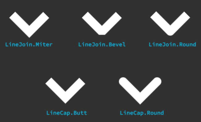
When you draw lines, the properties of LineJoin and LineCap control the styles of line joins and caps.
The following image illustrates the different styles of line caps and joins:

The following code snippet draws a zigzag line:

painter2D.lineWidth = 10.0f;
painter2D.strokeColor = Color.white;
painter2D.lineJoin = LineJoin.Round;
painter2D.lineCap = LineCap.Round;

painter2D.BeginPath();
painter2D.MoveTo(new Vector2(100, 100));
painter2D.LineTo(new Vector2(120, 120));
painter2D.LineTo(new Vector2(140, 100));
painter2D.LineTo(new Vector2(160, 120));
painter2D.LineTo(new Vector2(180, 100));
painter2D.LineTo(new Vector2(200, 120));
painter2D.LineTo(new Vector2(220, 100));
painter2D.Stroke();
Arc
You can use the following methods to draw arcs:
- The
Arcmethod generates an arc from the provided arc center, the radius, and the starting and ending angles. - The
ArcTomethod generates an arc between two straight segments.
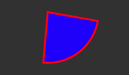
The following code snippet uses Arc to draws a sector with a border:

painter2D.lineWidth = 2.0f;
painter2D.strokeColor = Color.red;
painter2D.fillColor = Color.blue;

painter2D.BeginPath();
// Move to the arc center
painter2D.MoveTo(new Vector2(100, 100));

// Draw the arc, and close the path
painter2D.Arc(new Vector2(100, 100), 50.0f, 10.0f, 95.0f);
painter2D.ClosePath();

// Fill and stroke the path
painter2D.Fill();
painter2D.Stroke();
The following code snippet uses ArcTo to draw an arc of the requested radius in the corner of the lines:

painter2D.BeginPath();
painter2D.MoveTo(new Vector2(100, 100));
painter2D.ArcTo(new Vector2(150, 150), new Vector2(200, 100), 20.0f);
painter2D.LineTo(new Vector2(200, 100));
painter2D.Stroke();
Curves
You can use the following methods to draw curves:
- The
BezierCurveTomethod generates a cubic bezier curve by two control points and the final position of the cubic bezier. - The
QuadraticCurveTomethod generates a quadratic bezier curve by a control point and the final position of the quadratic bezier.
The following code snippet uses BezierCurveTo to draw a bezier curve:

painter2D.BeginPath();
painter2D.MoveTo(new Vector2(100, 100));
painter2D.BezierCurveTo(new Vector2(150, 150), new Vector2(200, 50), new Vector2(250, 100));
painter2D.Stroke();
The following code snippet uses QuadraticCurveTo to draw a quadratic curve:

painter2D.BeginPath();
painter2D.MoveTo(new Vector2(100, 100));
painter2D.QuadraticCurveTo(new Vector2(150, 150), new Vector2(250, 100));
painter2D.Stroke();
Holes in fills
You can construct paths with holes in them when you do a Fill. When you call MoveTo, it starts a new sub-path. To create a hole, use the fill rule to overlap the various sub-paths with each other.
The fill rule determines how to fill the inside of a shape:
-
OddEven: Draw a ray from that point to infinity in any direction and count the number of path segments from the given shape that the ray crosses. If this number is odd, the point is inside; if even, the point is outside. -
NonZero: Draw a ray from that point to infinity in any direction, and then examine the places where a segment of the shape crosses the ray. Start with a count of zero, and add one each time a path segment crosses the ray from left to right. Subtract one each time a path segment crosses the ray from right to left. After you count the crossings, if the result is zero, then the point is outside the path. Otherwise, it’s inside.
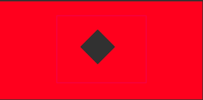
The following code snippet creates a rectangle with a diamond shape hole in it:

painter2D.BeginPath();
painter2D.MoveTo(new Vector2(10, 10));
painter2D.LineTo(new Vector2(300, 10));
painter2D.LineTo(new Vector2(300, 150));
painter2D.LineTo(new Vector2(10, 150));
painter2D.ClosePath();

painter2D.MoveTo(new Vector2(150, 50));
painter2D.LineTo(new Vector2(175, 75));
painter2D.LineTo(new Vector2(150, 100));
painter2D.LineTo(new Vector2(125, 75));
painter2D.ClosePath();

painter2D.Fill(FillRule.OddEven);