Warning
Warning: Unity Simulation is deprecated as of December 2023, and is no longer available.
What is a ToF Sensor?
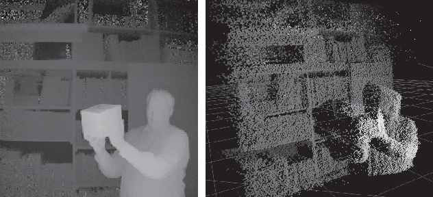
A Time of Flight (ToF) sensor works by emitting a pulsed light source, and observing the reflected light. The phase shift between the emitted and reflected light is then translated to distance. ToF sensors have diverse applications in industries such as robotics, automotive, autonomous vehicles, security, and gaming.
Our ToF sensor model uses the depth measured by a camera, in a similar manner to our depth-buffer camera. Read more here. The depth data is then converted to a point cloud.
Sensor Output
The ToF sensor outputs a point cloud corresponding to depth. All Unity sensors follow the ROS schema but are ROS-agnostic in how they serialize and send data.
The sensor outputs point cloud data in the following structure:
Schema
Header header
   uint32 seq
   time stamp        # Time of sensor data acquisition
   string frame_id   # the coordinate frame ID for the 3d points

# 2D structure of the point cloud. If the cloud is unordered, height is
# 1 and width is the length of the point cloud.
uint32 height
uint32 width

PointField[] fields  # the channels and their layout in the binary data blob.

bool    is_bigendian # Is the data big-endian in this computer architecture?
uint32  point_step   # Length of a point in bytes (3x4 = 12)
uint32  row_step     # Length of a row in bytes
uint8[] data         # Actual array of 3d points [{x,y,z}]

bool is_dense        # True if there are no invalid points
Unity Simulation Structure
public class PointCloud2Msg : Message
{
  public const string k_RosMessageName = "sensor_msgs/PointCloud2";
  public override string RosMessageName => k_RosMessageName;

  //  This message holds a collection of N-dimensional points, which may
  //  contain additional information such as normals, intensity, etc. The
  //  point data is stored as a binary blob, its layout described by the
  //  contents of the "fields" array.
  //
  //  The point cloud data may be organized 2d (image-like) or 1d (unordered).
  //  Point clouds organized as 2d images may be produced by camera depth sensors
  //  such as stereo or time-of-flight.
  //  Time of sensor data acquisition, and the coordinate frame ID (for 3d points).

  public Std.HeaderMsg header;

  //  2D structure of the point cloud. If the cloud is unordered, height is
  //  1 and width is the length of the point cloud.
  public uint height;
  public uint width;

  //  Describes the channels and their layout in the binary data blob.
  public PointFieldMsg[] fields;

  public bool is_bigendian; //  Is this data bigendian?

  public uint point_step;   //  Length of a point in bytes
  public uint row_step;     //  Length of a row in bytes
  public byte[] data;       //  Actual point data, size is (row_step*height)
  public bool is_dense;     //  True if there are no invalid points
}
Units: The point coordinates are in the Unity Scene's units, which default to meters but can be set to any user-defined unit.
Time of Flight Sensor Model
The ToF sensor model uses the depth measured by a camera, in a similar manner to the depth-buffer camera. Read more here. The depth data is then converted to a point cloud.
Sensor model implications
- The camera uses Unity's camera and reads the distance values directly from the depth buffer.
- The values in the depth buffer represent a nonlinear fraction of the distance between the near and far clip planes, so they are converted to actual distance values before being reported:
distance = near + (far - near)/depth_value. - The distances are finally converted to a point cloud and then published. The coordinates in the published point cloud are relative to the camera's local transform and are in the right-hand coordinate system.
Noise
Gaussian noise can be added to the output data of the sensor. This can be done by setting the noise type, mean and standard deviation.
Properties
| Property | Function | XML Element |
|---|---|---|
| Topic | The name of the topic to which point cloud data is published. Each sensor should publish to a unique topic. | sensor/topic |
| Image Topic | The name of the topic to which the rgb image is published. | sensor/camera/image/topic |
| Depth Topic | The name of the topic to which the depth image is published. | sensor/depth/topic |
| Update Rate | The update rate in hz is the frequency at which the sensor will generate data. |
sensor/update_rate |
| Offset Start Time | Determines if the sensor should offset its start time by a small, random number of frames. | sensor/offset_start_time |
| Enable Intensity | When enabled, the output point cloud will contain an intensity channel (XYZI). | sensor/camera/intensity_enabled |
| Intensity Value | When the "Enable Intensity" property is enabled, this constant value will be used for the intensity channel of the point cloud output (XYZI). Note that this sensor does not actually measure intensity. | sensor/camera/intensity |
| Enable Color | When enabled, the output point cloud will contain an RGBA channel (XYZC). If both color and intensity are enabled, the RGBA channel is after the intensity channel (XYZIC) | sensor/camera/color_enabled |
| Gamma Exponent | The exponent value for gamma correction of the color channel. gamma_corrected_rgb = raw_rgb^gamma_exp (default: 1.0/2.2 = 0.45) |
sensor/camera/gamma_exp |
| Image Width | The image width in pixels. | sensor/camera/image/width |
| Image Height | The image height in pixels. | sensor/camera/image/height |
| Horizontal FoV | The horizontal field of view of the sensor (radians in the description file, degrees in the Unity Inspector). | sensor/camera/horizontal_fov |
| Clip Near | The distance to the near clipping plane, in meters. | sensor/camera/clip/near |
| Clip Far | The distance to the far clipping plane, in meters. | sensor/camera/clip/far |
| Noise Type | The type of noise to add to the point cloud coordinates output. | sensor/noise/type |
| Noise Mean | The mean of the Gaussian distribution from which additive noise values are drawn. | sensor/noise/mean |
| Noise Stddev | The standard deviation of the Gaussian distribution from which additive noise values are drawn. | sensor/noise/stddev |
Import/Export example
You can import and export Unity sensors from an XML format similar to SDF. For more details refer to Import a vehicle model: Sensors. Here is an example of a ToF sensor.
<sensor name="tof_sensor" type="tof">
  <update_rate>30</update_rate>
  <topic>/unity/tof_pointcloud</topic>
  <camera>
    <intensity_enabled>true</intensity_enabled>
    <intensity>1</intensity>
    <color_enabled>false</color_enabled>
    <horizontal_fov>1.047</horizontal_fov>
    <image>
      <width>256</width>
      <height>256</height>
    </image>
    <clip>
      <near>0.1</near>
      <far>100<far>
    </clip>
  </camera>
</sensor>