Warning
Warning: Unity Simulation is deprecated as of December 2023, and is no longer available.
What is a depth camera?
A depth camera is a sensor that reports the distances to surrounding objects in an image format, where each pixel encodes a distance value.
We have two types of depth cameras: a depth-buffer camera and a stereo-depth camera. Each can output the same data types, but they differ in how they compute the depth data. Each has its advantages and disadvantages.
Sensor Output
Schema
# An uncompressed image.
# (0, 0) is at top-left corner of image
# +x points to the right in the image
# +y points down in the image
# +z points into to plane of the image

Header header
   uint32 seq
   time stamp        # the acquisition time of the image.
   string frame_id   # the optical frame of camera

uint32 height         # image height (number of rows)
uint32 width          # image width (number of columns)

string encoding       #  Encoding of pixels is always "32FC1":
                      #  one channel floating point with 32 bit precision

uint8 is_bigendian    # is this data big-endian?
uint32 step           # Full row length in bytes (width * 4)
uint8[] data          # actual matrix data, size = step * rows (i.e. width * height * 4)
Unity Simulation Structure
public class ImageMsg : IMessage
{
  public const string k_RosMessageName = "sensor_msgs/Image";
  public override string RosMessageName => k_RosMessageName;

  //  This message contains an uncompressed image
  //  (0, 0) is at top-left corner of image
  //  +x should point to the right in the image
  //  +y should point down in the image
  //  +z should point into to plane of the image

  public Std.HeaderMsg header;
  //  Header timestamp should be acquisition time of image
  //  Header frame_id should be optical frame of camera
  //  origin of frame should be optical center of cameara

  public uint height;  //  image height, that is, number of rows
  public uint width;   //  image width, that is, number of columns

  public string encoding;   //  Encoding of pixels is always "32FC1":
                            // one channel floating point with single precision

  public byte is_bigendian; //  is this data bigendian?
  public uint step;   //  Full row length in bytes
  public byte[] data; //  actual matrix data, size is (step * rows)
}
Encoding: Distance values are encoded as single-precision (32-bit) floating-point numbers.
Data: Distance values are serialized in a single-byte array.
Depth-buffer camera
Depth-buffer camera model
The depth-buffer camera is packaged within the CameraSensor and is enabled by setting the depth/enable parameter.
Sensor model implications
The depth-buffer camera uses Unity's camera and reads the distance values directly from the depth buffer.
The values in the depth buffer represent a nonlinear fraction of the distance between the near and far clip planes, so they are converted to actual distance values before being reported. (distance = near + (far - near)/buffer_value.)
Noise
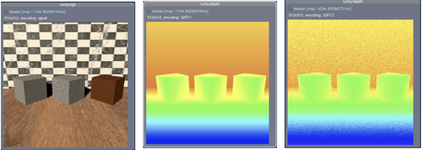
By default, the depth camera will report the "actual" distance per pixel computed from the normalized depth values in the depth buffer.
We support adding noise sampled from a Gaussian distribution independently per pixel. This can be enabled by setting the depth noise type parameter to gaussian and specifying the depth noise mean and standard deviation.
Properties
| Property | Function | XML Element |
|---|---|---|
| Update Rate | The update rate in hz is the frequency at which the sensor will generate data. |
sensor/update_rate |
| Camera | The camera component used to capture data. | |
| Horizontal FOV | The horizontal field of view of the camera (radians in the description file, degrees in the Unity Inspector). | sensor/camera/horizontal_fov |
| Image Width | The image width in pixels. | sensor/camera/image/width |
| Image Height | The image height in pixels. | sensor/camera/image/height |
| Clip Near | Near clipping plane of the camera. | sensor/camera/clip/near |
| Clip Far | Far clipping plane of the camera. | sensor/camera/clip/far |
| Enable Depth Output | Enable depth image output. | sensor/depth/enable |
| Enable Camera Info Output | Enable camera information output. | sensor/camera_info/enable |
| Enable Camera Info Depth Output | Enable camera depth information output. | sensor/camera_info/depth/enable |
| Render Every Frame | Whether to render the camera automatically each unity update. Publishing will still happen at the update rate. | |
| Camera Noise Type | The type of noise to generate onto within the RGB output. | |
| Camera Noise Mean | The mean of the Gaussian distribution from which additive noise values are drawn within the RGB output. | |
| Camera Noise Stddev | The standard deviation of the Gaussian distribution from which additive noise values are drawn within the RGB output. | |
| Depth Camera Noise Type | The type of noise to generate onto within the depth output. | |
| Depth Camera Noise Mean | The mean of the Gaussian distribution from which additive noise values are drawn within the depth output. | |
| Depth Camera Noise Stddev | The standard deviation of the Gaussian distribution from which additive noise values are drawn within the depth output. | |
| Image Publisher Topic | The name of the topic on which RGB image data is published. | sensor/topic |
| Depth Publisher Topic | The name of the topic on which depth image data is published. | sensor/camera/depth/topic |
| Camera Info Publisher Topic | The name of the topic on which camera info data is published. | sensor/camera_info/topic |
| Depth Camera Info Publisher Topic | The name of the topic on which depth camera info data is published. | sensor/camera_info/depth/topic |
Import/Export example
You can import and export a depth-camera sensor from an XML format similar to the example below:
<sensor name="depth-camera" type="camera">
  <update_rate>30</update_rate>
  <topic>/unity/depth_camera</topic>
  <camera>
    <horizontal_fov>1.047</horizontal_fov>
    <image>
      <width>256</width>
      <height>256</height>
    </image>
    <clip>
      <near>0.1</near>
      <far>100</far>
    </clip>
  </camera>
  <depth>
    <enable>true</enable>
    <noise>
      <type>gaussian</type>
      <mean>0.0</mean>
      <stddev>0.07</stddev>
    </noise>
  </depth>
</sensor>
Stereo-depth camera
Stereo-depth camera model
"Depth-from-stereo" is a computer-vision algorithm inspired by the human binocular vision system. The stereo-depth sensor calculates depth by estimating disparities between matching key‑points (patches) in the left and right images from a stereo pair.
Stereo matching performs calculation of disparity between pixels on the left and right image and uses that to estimate depth (distance to the camera).
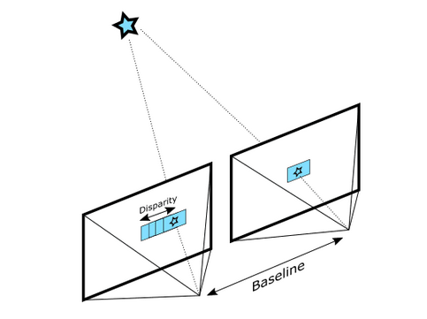
To measure disparity for each pixel coordinate, the similarity of a patch (block) of pixels centered at that pixel coordinate in the left image is measured against every patch within a horizontal neighborhood of that coordinate in the right image in order to search for the most similar patch. The difference between the pixel coordinate on the left image and the best match on the right image is the disparity. Depth is calculated from disparity using the following equation:
depth = baseline X focal_length / (disparity X pixel_size)
The baseline is the distance between the two cameras and the focal_length is the focal length of the cameras. Both are parameters of the sensors. The pixel_size is the width of each pixel in the projected image - calculated as the physical width of the whole projected image divided by its width in pixels (horizontal resolution).
Since a simulated camera doesn't have a real lens, we pretend the near clipping plane is the projected image: the focal length is the near clip distance and the width of the projected image is near_clip_distance X sin(horizontal_fov/2) X 2.
The size of the patch (patch_size), the search neighborhood (min_disparity and max_disparity), the acceptable similarity (min_score and max_score) can also be specified as the parameters of the stereo-camera sensor.
Sensor model implications
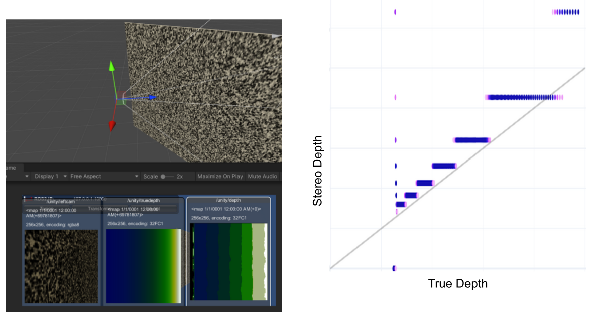
In the depth equation, depth = baseline X focal_length / (disparity X pixel_size), all factors except for disparity are constant parameters of the sensor model. So the equation is in the form of y = c / x, where y is the depth, x is disparity and c = baseline X focal_length / pixel_size. Since x is disparity in pixel units, it is always an integer value, so the calculated stereo depth will always be discretized as there is no sub-pixel accuracy for disparity. This plot can help with better understanding. This will result in banding artifacts in the calculated stereo depth similar to the example shown below:
Noise
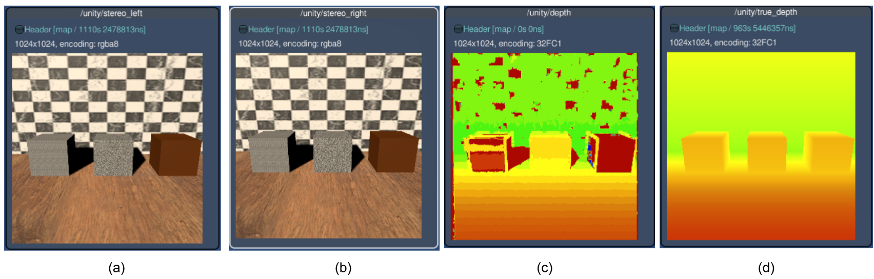
The previous (depth-based) camera sensor was implemented to use ground-truth depth values, so random values from a Gaussian distribution must be added to achieve a more realistic, noisy output. On the other hand, in this stereo-depth camera implementation, noise occurs naturally as an inherent aspect of the algorithm. The accuracy of the depth estimations highly depends on the density of visually distinguishable points (features) that can be matched. Whenever there are visual occlusions (lack of data) or there are no unique visually distinguishable features (low confidence) between left and right images, there will be holes in the calculated depth. The most common cases are:
- Edge shadows: When the left and the right images do not see the same object due to shadowing (aka occlusion). Since we reference everything to the left image, you will see this shadowing on the left side of objects, and along the left edge of the image.
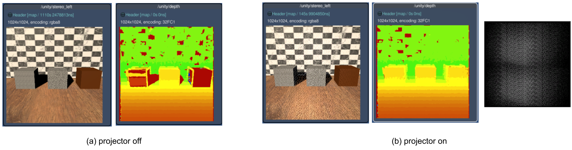
- Lack of features to find matches: Stereo matching relies on matching texture in the left and right images, so for texture-less surfaces like a flat white wall, the depth estimate can be challenging. This case can be improved by using a projector (see next section) to generate textures.
- Incorrect matches due to repeating patterns: This happens when there are multiple equally good matches, such as when looking at a very uniform periodic structure.
- No data/signal: If the images are under-exposed or over-exposed due to lack of light or spot lights on shiny surfaces.
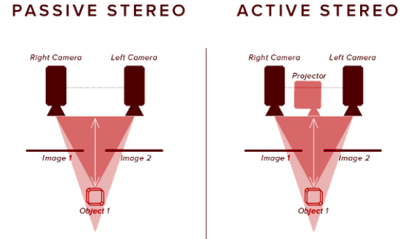
Active Stereo using a Projector
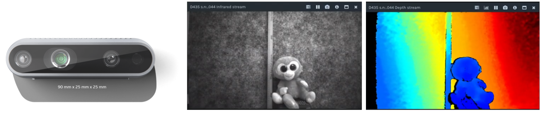
As stated above, any source of visual texture will significantly improve the accuracy of the depth estimations. Stereo-based depth cameras such as the Intel RealSense™ D435 utilize an infrared texture projector that can add details outside of the visible spectrum as well as act as an artificial source of light for nighttime or dark situations.
Configuring texture projectors
The projector for the stereo-depth sensor is modeled using a spotlight with a cookie texture and is placed in a GameObject named StereoProjector under the StereoCameraSensor. Configurations are currently only possible using the Inspector view inside the Unity Editor.
Properties
| Property | Function | XML Element |
|---|---|---|
| Update Rate | The update rate in hz is the frequency at which the sensor will generate data. |
sensor/update_rate |
| Offset Start Time | Determines if the sensor should offset its start time by a small, random number of frames. | sensor/offset_start_time |
| Image Width | The image width in pixels. | sensor/camera/image/width |
| Image Height | The image height in pixels. | sensor/camera/image/height |
| Horizontal FOV | The horizontal field of view of the left and right cameras (in radians). | sensor/camera/horizontal_fov |
| Near Plane | Near clipping plane of the camera. | sensor/camera/clip/near |
| Far Plane | Far clipping plane of the camera. | sensor/camera/clip/far |
| Sync Projector | Determines if the projector's angle should be synced to the camera's horizontal FOV or not. | sensor/camera/sync_projector |
| Left Camera | The input left camera. | |
| Right Camera | The input right camera. | |
| Flip Y | Determines if the output image should be flipped across the y axis or not. | sensor/stereo/flip_y |
| Patch Size | How large a block of pixels (width and height) to examine while looking for a match between the left and right eye. Larger block sizes increase overall accuracy but are more expensive. It must be an odd number >=1; typically a value in the 5-17 range is good enough. Note, changing patch_size affects score values because it determines the number of pixels that contribute to each score. So if you increase this, consider increasing max_score as well. | sensor/stereo/patch_size |
| Min Disparity | Minimum possible disparity value. A disparity of 0 implies the target is "infinitely" far away, or at least too far to get a useful depth reading, so typically this is set to 1. | sensor/stereo/min_disparity |
| Max Disparity | Maximum possible disparity value. Higher max disparity results in matching closer objects, at the cost of increased processing time. Normally, a value within the 32-64 range works well. | sensor/stereo/max_disparity |
| Min Score | Reject depth values with suspiciously good match quality (probably signifying the image is featureless). (lower score = more similar). Set to 1 by default, i.e. don't reject unless the image is totally featureless. | sensor/stereo/min_score |
| Max Score | Reject depth values with poor match quality. (higher score = less similar). For a patch size of 17 we recommend a max_score of around 64000; if you change the patch size you may need to adjust this. | sensor/stereo/max_score |
| Uniqueness Ratio | Reject depth values if the second-best disparity score is within this % of the best score. Set to 0 to completely ignore this factor. Valid range is [0,100] but normally, a value within the 10-50 range works well. | sensor/stereo/uniqueness_ratio |
| Stereo Depth Topic | The name of the topic on which stereo depth image data is published. | sensor/topic |
| True Depth Topic | The topic to which the true depth image is published. Meant for debugging. | sensor/stereo/true_depth_topic |
| Depth Error Topic | The topic to which the difference between the true depth and the estimated stereo depth image is published. Meant for debugging. | sensor/stereo/depth_error_topic |
| Left Camera Topic | The topic to which the left camera image is published. Meant for debugging. | sensor/stereo/left_camera_topic |
| Right Camera Topic | The topic to which the right camera image is published. Meant for debugging. | sensor/stereo/right_camera_topic |
| Left Camera Info Topic | The name of the topic on which the stereo camera's left camera info data is published. | sensor/stereo/camera_info/left/topic |
| Right Camera Info Topic | The name of the topic on which the stereo camera's right camera info data is published. | sensor/stereo/camera_info/right/topic |
Import/Export example
You can import and export Unity sensors from an XML format similar to the example below:
<sensor name="depth-camera" type="camera">
  <update_rate>30</update_rate>
  <topic>/unity/stereo_camera</topic>
  <camera>
    <horizontal_fov>1.047</horizontal_fov>
    <image>
      <width>256</width>
      <height>256</height>
    </image>
    <clip>
      <near>0.3</near>
      <far>100</far>
    </clip>
  </camera>
  <stereo>
    <patch_size>17</patch_size>
    <min_disparity>1</min_disparity>
    <max_disparity>32</max_disparity>
    <min_score>1</min_score>
    <max_score>64000</max_score>
    <uniqueness_ratio>0</uniqueness_ratio>
    <baseline>0.05</baseline>
  </stereo>
</sensor>