Warning
Warning: Unity Simulation is deprecated as of December 2023, and is no longer available.
Import a vehicle model
Another way to get your vehicle model into Unity is to import it from an XML format similar to SDF. The Simulation Description Format (SDF) is a set of nested XML tags that define an ego vehicle including the geometry, physical properties, sensors, and controllers. Out of the family of the SDF-like formats, Unity only supports import of the URDF format at the moment.
How to import a URDF file
Pre-reqs
Before you import the XML file, you'll want to check a few things to ensure the import process goes smoothly.
- Create a single URDF: You'll need to have a single
.urdffile with relative paths to any included mesh files, like.stl,.objor.fbx. - Check the file paths: Make sure the
.urdffile is at the root-level of your directory (see below for an example file hierarchy) and all paths to files and associated geometry are beneath it with a relative path. Any references to//packagewill be resolved to be a relative path.
Your .urdf path should look something like the following:
robot_descriptioon
|-- robot_description
|    |-- meshes
|    |    |-- visual
|    |    |    |-- robot_base.stl
|    +-- robot.urdf
- Put the files in the Unity project: Add your folder containing the
.urdfinto your Unity project's Assets directory. As soon as Unity detects a new.urdffile in the project, it will be imported automatically and made available as a prefab in the Project tab.

Prefabs
Once you have a prefab, you can instantiate it in any scene by dragging it from the Project tab to the Scene view, or to the Hierarchy view. From there, you can add new components to any GameObjects, change any properties but you shouldn't delete any parts of the hierarchy, since that is a destructive action that breaks the connection between this instance and the prefab it's been instantiated from.
The prefab connection is useful in case you might want to make changes to the source urdf file later, as Unity listens to changes and once there is a modification detected, a new import is run automatically. It's a non-destructive process that updates all the prefab instances in all scenes and aims at automatically merging your changes with the new version of the prefab.
Import settings
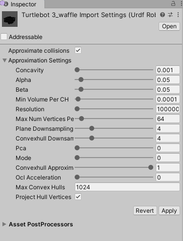
The import settings can be viewed and changed per each urdf file by clicking on the urdf asset in the Project tab. The settings appear in the Inspector tab. Currently, the only available option is Approximate Collisions, which is enabled by default. The approximation settings are only shown in case Approximate Collisions is enabled.

The Approximate Collisions option only affects mesh geometries for Colliders.
When enabled, a set of convex hulls that approximates the shape of the source mesh is built automatically. This is needed because only convex meshes can be used with Rigidbodies and ArticulationBodies, due to a limitation in the physics engine used under the hood. You can read more on convex decompositions here.
When disabled, Unity only calculates a convex hull for the source mesh. This improves the import times significantly, but can result in poor Collider fits to the source geometry, especially in case of the robotic arms where meshes are usually highly detailed.

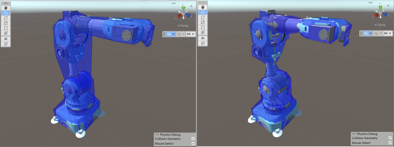
In the figure above, you can see a comparison of the collision geometry built with both values of the approximation setting. On the left, no approximation is used and the gap between the collision geometry (shown in blue) and the visual geometry is rather large. On the right, convex approximation is used so the fit is much tighter. The result on the left was imported almost instantly, whereas the right one took about 5 seconds to import. There is no such performance difference at run-time, though.
Unity currently supports the following URDF concepts:
Links
Links have geometry and associated visual, inertial, and collision information.
URDF represents them as XML tags like this:
  <link name="base_link">
    <inertial>
      <origin rpy="0 0 0" xyz="0 0 0" />
      <mass value="1" />
      <inertia ixx="0.4" ixy="0" ixz="0" iyy="0.4" iyz="0" izz="0.12" />
    </inertial>
    <visual>
      <geometry>
        <box size="0.6 0.1 0.2"/>
      </geometry>
    </visual>
    <collision>
      <geometry>
        <box size="0.6 0.1 0.2"/>
      </geometry>
    </collision>
  </link>
Unity maps each link to a GameObject with an ArticulationBody component. Then, the visual and collision tags become child subtrees attached to that GameObject as following:
Primitive Visual geometries (
<box>,<cylinder>,<sphere>) become Unity primitives. Mesh geometry gets mapped to a hierarchy of GameObjects (depending on the internal complexity of that mesh, as authored in a DCC Tool). A wide variety of mesh formats is supported (.obj,.stl,.fbx, etc).Some primitive Collision (
<box>,<sphere>) geometries are mapped to the corresponding primitive Colliders (such as BoxCollider, SphereCollider). However, the cylinder geometry is mapped to a convex MeshCollider that uses a built-in Unity mesh for the cylinder due to a limitation in the physics engine. The Mesh geometries are mapped either to one convex MeshCollider using the source mesh (in case no convex decomposition is used), or to a set of convex MeshColliders (in case convex decomposition was used to produce a tighter convex approximation of the source mesh).Inertial tags become properties of the ArticulationBody in Unity. Currently, only the mass property is applied, whereas the inertia tensor will always be calculated from the geometries, poses, and mass automatically. In case you still need to override the inertia tensor manually on a few ArticulationBodies, there is a property to do that from script.
Joints
Joints in URDF list two links and supply a constraint to describe how two physical bodies are connected and allowed to move with respect to each other. The following joints types are supported:
- Continuous, a continuous hinge joint that rotates around the axis and has no upper and lower limits. It maps to the Revolute joint type with free rotation in the ArticulationBody.
- Revolute, a hinge joint that rotates along the axis and has a limited range specified by the upper and lower limits. It maps to the Revolute joint type with limited rotation in the ArticulationBody.
- Prismatic, a sliding joint that slides along the axis, and has a limited range specified by the upper and lower limits. It maps to the Prismatic joint type with limited linear motion in the ArticulationBody.
- Fixed, a joint with zero degrees of freedom that rigidly connects two links. It maps to the Fixed joint type in the ArticulationBody.
However, these URDF joint types are not supported currently:
- Floating, this joint allows motion for all 6 degrees of freedom. It is advised to make a separate ArticulationBody hierarchy for this.
- Planar, this joint allows motion in a plane perpendicular to the axis. It is advised to use two ArticulationBodies parented to each other, both using a Prismatic joint with motion axes perpendicular to the axis.
Sensors
Sensors in SDF are specified using <sensor> tags. They can be attached to any link of the robot hierarchy and provide the ability to simulate different sensors used in a robot. You can use the SDF format to import a myriad of sensors supported by the SimulationSensors package which include:
- IMU, a sensor that broadcasts the linear acceleration and angular acceleration of the body it is attached to.
- Physics LiDAR, a sensor that broadcasts distance information of object around it using Unity's RayCast API. It can simulate a 3D LiDAR with output in the form of a point cloud or a 2D LiDAR with output in the form a laser scan.
- Raster LiDAR, a sensor that broadcasts the distance of objects around it. It simulates a LiDAR sensor type by rendering depth images, sampling the ray points, and converting those to world positions.
- Raytraced LiDAR, a sensor that broadcasts distance information of object around it using the Vulkan API. It can simulate a 3D LiDAR with output in the form of a point cloud or a 2D LiDAR with output in the form a laser scan.
- Parallel Stereo Camera, this sensor calculates the distance of the objects around it by simulating a stereo camera.
- Joint Sensor, a sensor that is attached to the base of the robot. This sensor broadcasts the joint position of all joints of the robot in reduced coordinate space to ROS.
- Camera Sensor, a sensor that simulates a camera on a robot and broadcasts RGB as well as Depth images.
- Fisheye Camera Sensor, a sensor that simulates a camera with ultra wide-angle lens.
Sensors can be nested inside link tags to add sensor configuration to a vehicle. The following shows how a camera sensor can be attached to the base_link of a robot. Keep in mind that if the sensor is expected to have mass or visuals you will want to add <inertial>, <collision> or <visual> tags to the sensor's link as well. For a full detailed breakdown of the sensor, format check out the sensors documentation.
<link name="base_link">
    <sensor name="rgb-camera" type="camera">
        <update_rate>30</update_rate>
        <topic>/unity/rgb</topic>
        <camera>
            <horizontal_fov>1.047</horizontal_fov>
            <image>
                <width>256</width>
                <height>256</height>
            </image>
            <clip>
                <near>0.1</near>
                <far>100</far>
            </clip>
            <noise>
                <type>gaussian</type>
                <mean>0.0</mean>
                <stddev>0.02</stddev>
            </noise>
        </camera>
    </sensor>
</link>
💡 How do I import .xacro files?
The Unity importer only supports import of URDF files.\n\nURDF files are just XML, and oftentimes that can get repetitive—to solve this, the ROS world made another file format called
.xacro.
.xacrofiles are templated versions of URDF. In order to import them, you will first need to convert them into a single URDF file. Check out our guide on how to do this.