Warning
Warning: Unity Simulation is deprecated as of December 2023, and is no longer available.
Advanced Lidar Features
We offer advanced features for the Raytraced lidar to refine your sensor model. Note that these features are only compatible with the Raytraced Lidar.
Scan Patterns
Some lidars use a MEMS (micro-electromechanical system) to steer the laser beam instead of a DC motor. To emulate this functionality, set the Movement Technology to MEMS and select a Scan Pattern. There are three provided scan patterns:
- Circular Scan Pattern: rotates the LiDAR about the y-axis like a DC motor
- Cat Scan Pattern: the same thing as the Circular Scan Pattern, but also rotates the LiDAR about the local x-axis on a sine wave
- Stationary Scan Pattern: simulates no movement on any axis
Custom scan patterns can be implemented by creating a new class that inherits from ScanPattern, adding the CreateAssetMenu attribute to the class, and overriding the function GetRotationAtTime.
Once you've created a custom scan pattern, navigate to the menu option you specified in the CreateAssetMenu attribute and select it to create a ScanPattern ScriptableObject for use with the RayTraced LiDAR.
For example, here is what the default CircularScanPattern script looks like:
[CreateAssetMenu(menuName = "Simulation/Sensors/Scan Patterns/Circular Pattern")]
public class CircularScanPattern : ScanPattern
{
    /// <summary>
    /// Evaluates to a rotation that sweeps in a standard circular pattern.
    /// </summary>
    /// <param name="time">Elapsed time, in seconds</param>
    /// <param name="sweepFrequency">The rotational frequency of the LiDAR.</param>
    /// <returns></returns>
    public override Quaternion GetRotationAtTime(float time, float sweepFrequency)
    {
        var yaw = 2 * Mathf.PI * sweepFrequency;
        return Quaternion.AngleAxis(time * yaw * Mathf.Rad2Deg, Vector3.up);
    }
}
Warning
Custom scan patterns must return the same rotation value at the start and end of each sweep.
For example, the circular scan pattern returns an Euler angle of (0, 0, 0) at time 0s and 1s with a sweepFrequency of 1. Otherwise, unexpected behavior will occur.
Custom Laser Configuration
The LiDAR's laser distribution and firing times are configurable. By default, when no laser configuration is provided, the LiDAR will assume a spherical laser configuration using an evenly spaced 2D-array of beams based on the Horizontal Samples and Vertical Samples values, ordered in columns starting from the lowest elevation to the highest, with evenly-spaced beam firing times.
If a spherical configuration doesn't suit your needs, you can specify a laser configuration by setting a LaserConfigAsset in the LiDAR's Inspector window. This LaserConfigAsset will define the laser distribution and firing times of one single firing sequence, which is the process of cycle-firing all lasers in the LiDAR. A full LiDAR sweep (equivalent to one full rotation, or one message) usually contains multiple firing sequences.
By default, the RayTracedLidar simulates DC motor movement. As described in the Scan Patterns documentation, this Movement Technology can be set to MEMS in order to use a custom scan pattern. This is where you can use the Stationary Scan Pattern that does not simulate any spinning motion, which may be desirable for some custom laser configurations.
Each entry in the LaserConfigAsset defines a single beam's direction as well as firing time, so the number of Laser Config Entries directly equates to the number of beams defined in a single firing sequence. Multiple firing sequences in a single LiDAR sweep are supported, but the number of firing sequences must be a whole number greater than zero.
The number of firing sequences in a single LiDAR sweep is only indirectly configurable. If your laser configuration defines a firing sequence (i.e. the time for each beam is non-zero), the number of firing sequences in a sweep is equal to
1 / LiDAR Rotation Frequency / Total Firing Sequence Length.If the config does not contain a firing sequence, the number of firing sequences in a sweep is calculated based on the laser configuration's
Azimuth Resolution / LiDAR Horizontal Samples.
There are template Laser Configs describing common laser distributions, customizable for your use cases. These can be generated by right clicking in the Project window and navigating to Create > Simulation > Sensors > Laser Configs and selecting the desired template.
Grid Laser Config
This laser configuration makes a rectangular grid distribution perpendicular to the forward vector of the LiDAR (Z+).
| Component | Description |
|---|---|
| Firing Sequence Length | Time, in seconds, of the time it takes to cycle-fire all lasers once. |
| X Start | Position, in meters, of the first laser on the X axis, looking at Z+. |
| X Step | Distance, in meters, between lasers on the X axis, looking at Z+. |
| X Count | Number of lasers on the X axis, looking at Z+. |
| Y Start | Position, in meters, of the first laser on the Y axis, looking at Z+. |
| Y Step | Distance, in meters, between lasers on the Y axis, looking at Z+. |
| Y Count | Number of lasers on the Y axis, looking at Z+. |
If any of these components are modified, you will need to click the Regenerate laser config entries button in the config's Inspector to repopulate the laser config entries based on the new values.
Frustum Laser Config
This laser configuration makes a frustum distribution of the laser from a center point defined by the LiDAR position.
| Component | Description |
|---|---|
| Firing Sequence Length | Time, in seconds, of the time it takes to cycle-fire all lasers once. |
| Fov Axis | Specifies whether Fov is the horizontal or vertical field of view. |
| Fov | Field of view, in degrees. |
| Resolution X | Number of laser beams horizontally. |
| Resolution Y | Number of laser beams vertically. |
If any of these components are modified, you will need to click the Regenerate laser config entries button in the config's Inspector to repopulate the laser config entries based on the new values.
Single Forward Laser Config
This laser configuration makes a single laser beam pointing forward (Z+).
Custom Laser config
If the above templates don't suit your use case, you can create a fully custom distribution defining the angle and timing for each beam individually.
To create a new LaserConfigAsset without using one of the above templates, you can import a .laserconfig JSON-like file into the project with the proper components (described below); or, in the Project window, you can right-click and go to Create > Simulation > Sensors > LaserConfigAsset to create the file from scratch.
Each entry of the LaserConfigAsset has a series of components, as described below:
| Component | Description |
|---|---|
| Azimuth Resolution | The number of beams positioned in the XZ plane for one firing sequence; i.e. the number of unique columns defined by this configuration. |
| Elevation Offsets | Angle of each beam from the sensor's forward vector (Z+) on the elevation plane (YZ plane), in degrees. |
| Azimuth Offsets | Angle of each beam from the sensor's forward vector (Z+) on the azimuth plane (XZ plane), in degrees. |
| Firing Sequence | Elapsed time for each beam firing since the controller triggered a firing sequence, in seconds. |
| Has Firing Sequence | True if the Firing Time for each beam is defined as a non-zero, positive value. This value is automatically set based on the rest of the configuration. |
The resulting laserconfig file may look something like this:
{
    "azimuthResolution": 4,
    "elevationOffsets": [
        45.1,
        45,
        44.9,
        ...
    ],
    "azimuthOffsets": [
        11.15,
        3.67,
        -10.807,
        ...
    ],
    "firingSequence": [
        0,
        0.000002,
        0.0000045,
        ...
    ]
}
Material Spectroscopy
Material Spectroscopy is a feature developed to enhance the accuracy of material modeling by taking into account the spectrometry characteristics of a material. With this tool, you can modify the LiDAR wavelength to observe how the intensity changes for particular materials.
Material Spectroscopy does not change the x, y, and z components of the point cloud data, but instead calculates intensity based on set parameters, which are albedo, specular, shininess and the texture color's red channel. The parameters are based on a non-PBR (non - Physically Based Rendering) model.
The intensity is calculated using the following formula:

where

and

where theta is the angle between the incident light and the normal direction and alpha is the angle between the reflected direction and view direction.
To use Material Spectroscopy, follow these steps:
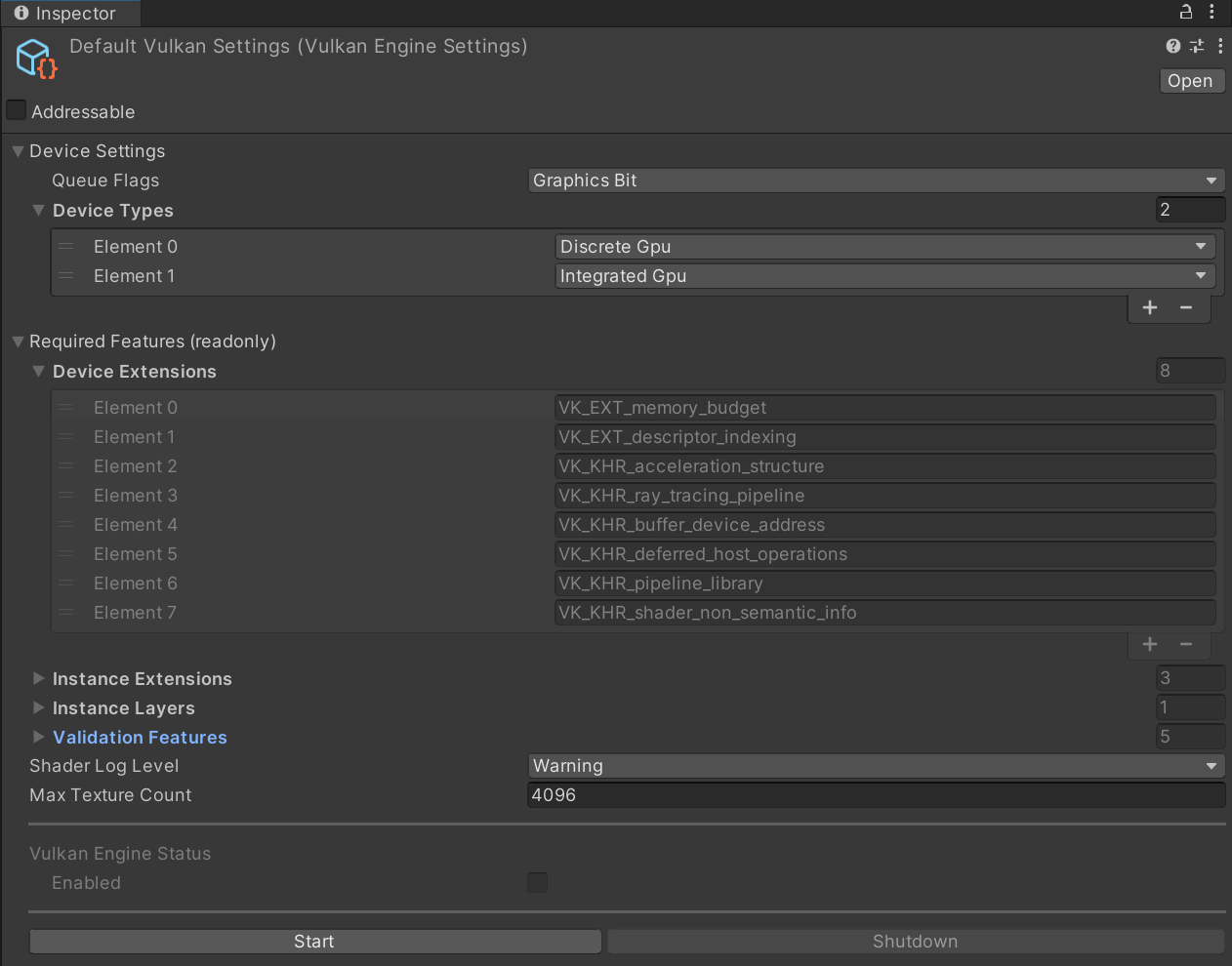
Configure Default Vulkan Settings
- Ensure that there is an instance of the RayTracingService prefab in the scene. Click on it to open its inspector and click on
DefaultVulkanSettings. - Make sure that
Queue Flagsis set toGraphics Bit, and that you have one or both ofDiscrete GPUandIntegrated GPUinDevice Types - Change the
Shader Log LeveltoInfoif you want to see messages from the Vulkan Shaders. If needed, modify the
Maximum Texture Count, which defines the maximum number of textures in the scene that Vulkan supports. This will be device specific. Finding the upper limit will require experimentation.Inspector view of Vulkan Settings
- Ensure that there is an instance of the RayTracingService prefab in the scene. Click on it to open its inspector and click on
Configure the lidar's wavelength and intensity
- Within the Raytraced Lidar's inspector, change the
WavelengthandIntensityto the desired values
- Within the Raytraced Lidar's inspector, change the
Create a spectrometry file
- This will be a file that corresponds to the material's albedo at different wavelengths. The file should contain a list of floats with each value on a new line. The wavelength corresponding to each albedo value should be at equal intervals. A resource for spectra for different common materials can be downloaded here.
- Our intensity algorithm uses a Hermite interpolation for wavelength values between values in the spectrometry file. If the value is outside of the range covered, it will clip to the edge values.
- The file's extension should be .spec
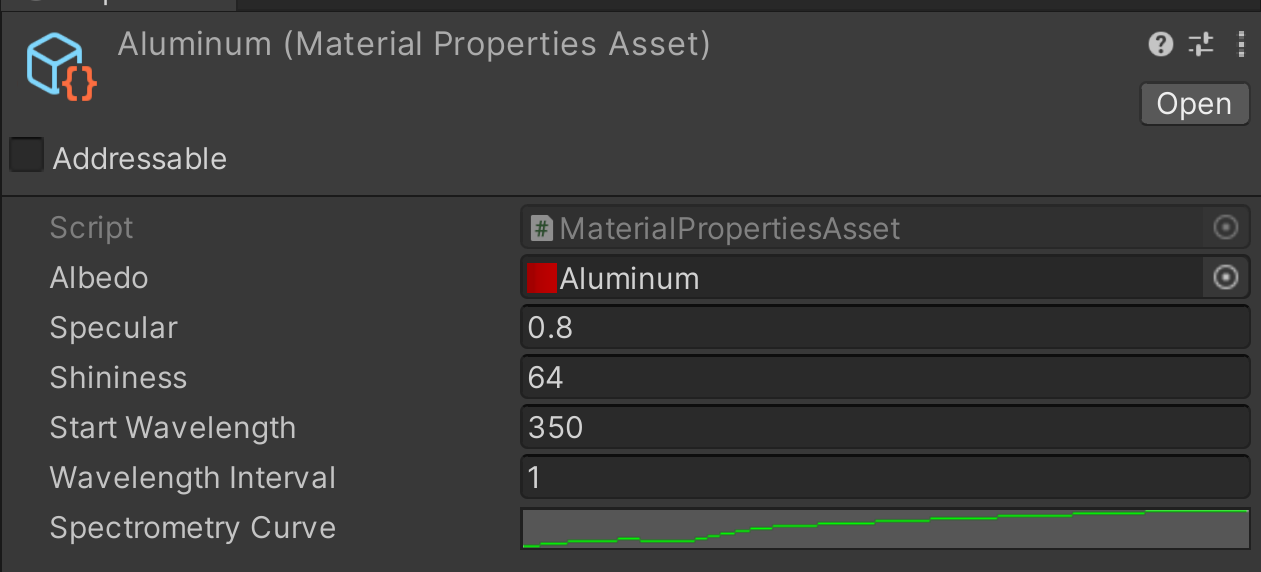
Create a Custom Material Property
In the project window, right-click and go to Create > Simulation > Sensors > CustomMaterialProperty. Drag the spectrometry file you just created to the
Albedofield. Fill in the values forSpecularandShininess. InStart Wavelength, enter the wavelength where the first line in the spectrometry file corresponds to. InWavelength Interval, add the wavelength step in the spectrometry file. The Spectrometry Curve shows a rendering of theAlbedofile. Modifying the curve will not modify the albedo; it is simply a rendering.Inspector view of Aluminum Custom Material Settings
Add a SensorMaterial Component
- Add a SensorMaterial component to the meshes where you want to specify a spectrometry by clicking Add Component in the inspector and searching for SensorMaterial.
- Alternatively, add it to every mesh in the scene by going to Simulation > Sensors > Add Default Sensor Material to Mesh Filters (at the top of the Editor).
- Drag the CustomMaterialProperty you just made into the
CustomMaterialPropertyfield - Drag the Texture corresponding to the material into the
Texturefield. Note that the intensity calculation will only be based on the red channel of the texture map.
Warning
The texture you drag into the SensorMaterial component will not implicitly match the Base Texture of the object's material.
Make sure you have assigned the Texture value correctly.
Warning
Make sure that the Read/Write property of the texture is set to true.
To do this, double click on the texture to open its inspector and check the Read/Write value under Advanced.
If a SensorMaterial is not added to every mesh, a default SensorMaterial, will be added automatically. If you want to see more verbose console logging (such as warnings when a default SensorMaterial is added, when a CustomMaterialProperty is missing, etc.), enable Enable Material Spectroscopy Logging in the scene's RayTracingService object.
You can visualize the intensity by following these steps.
We have also provided a library of Spectrometies, CustomMaterialProperties, Textures, and Materials of common materials. These can be found in the Samples at Advanced > Material Spectroscopy.
Point Cloud Motion Correction
If a LiDAR is moving during sample acquisition, the samples will be distorted. This matches how a real-life LiDAR works. This is caused by the fact that the origin of the beams changes while a lidar is making a sweep. The PointCloudMotionCorrection component lets you see data without this distortion to establish a sort of "ground truth" . The component "undoes" the distortion by using linear interpolation to change all points to be represented in the same frame of reference as the last position of the sweep. Its important to note that the point cloud is corrected post-acquisition, rather than a deterministic or retrospective correction.
The image below shows how the correction works. Assume that the lidar is sweeping counterclockwise, and is moving towards the item that it is hitting. T0 through T2 represent the times where individual beams are fired. You can see that the resulting point cloud is distorted. The motion corrected point cloud expresses all points from the last frame of reference.
Note that only a counterclockwise lidar rotation is supported.
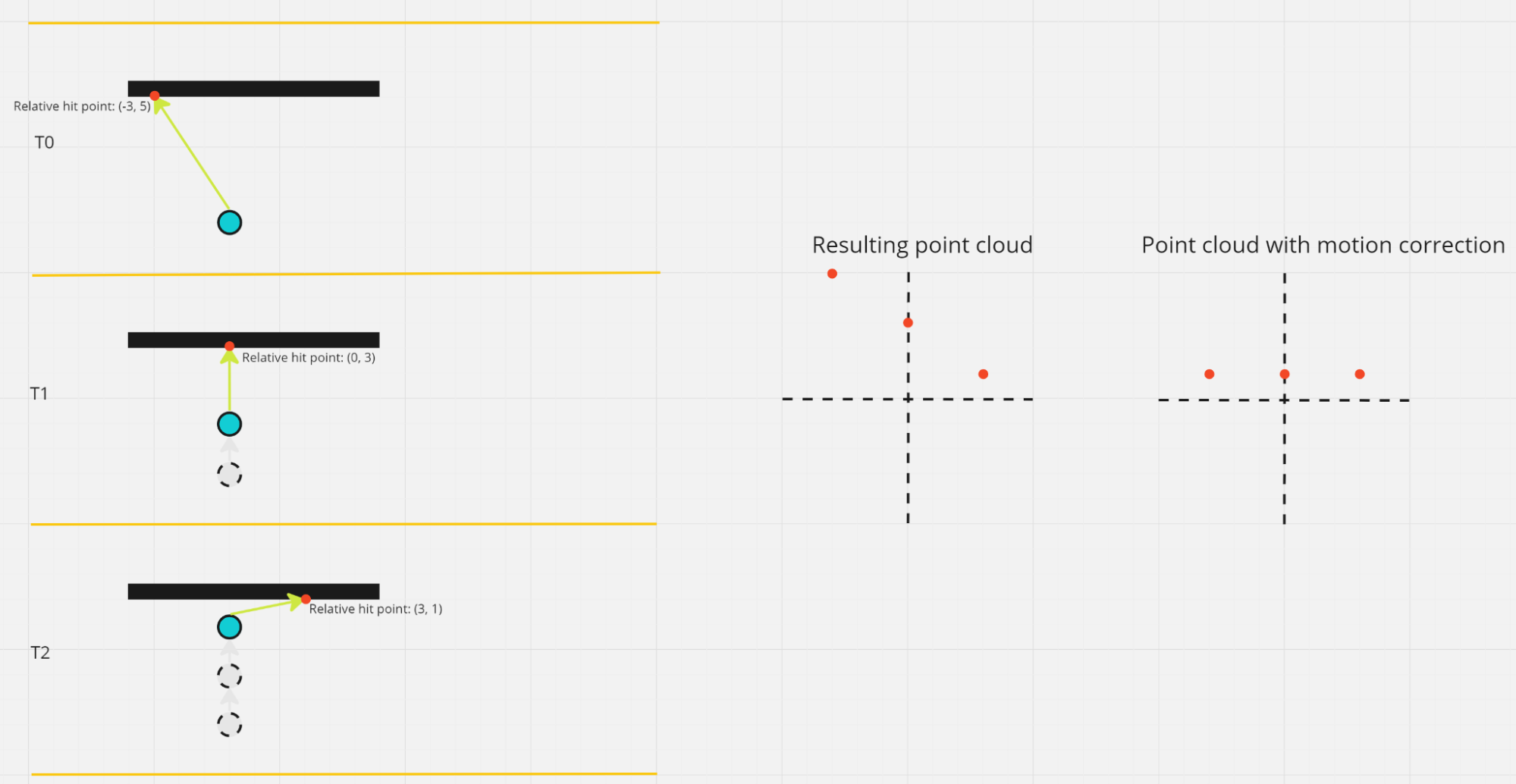
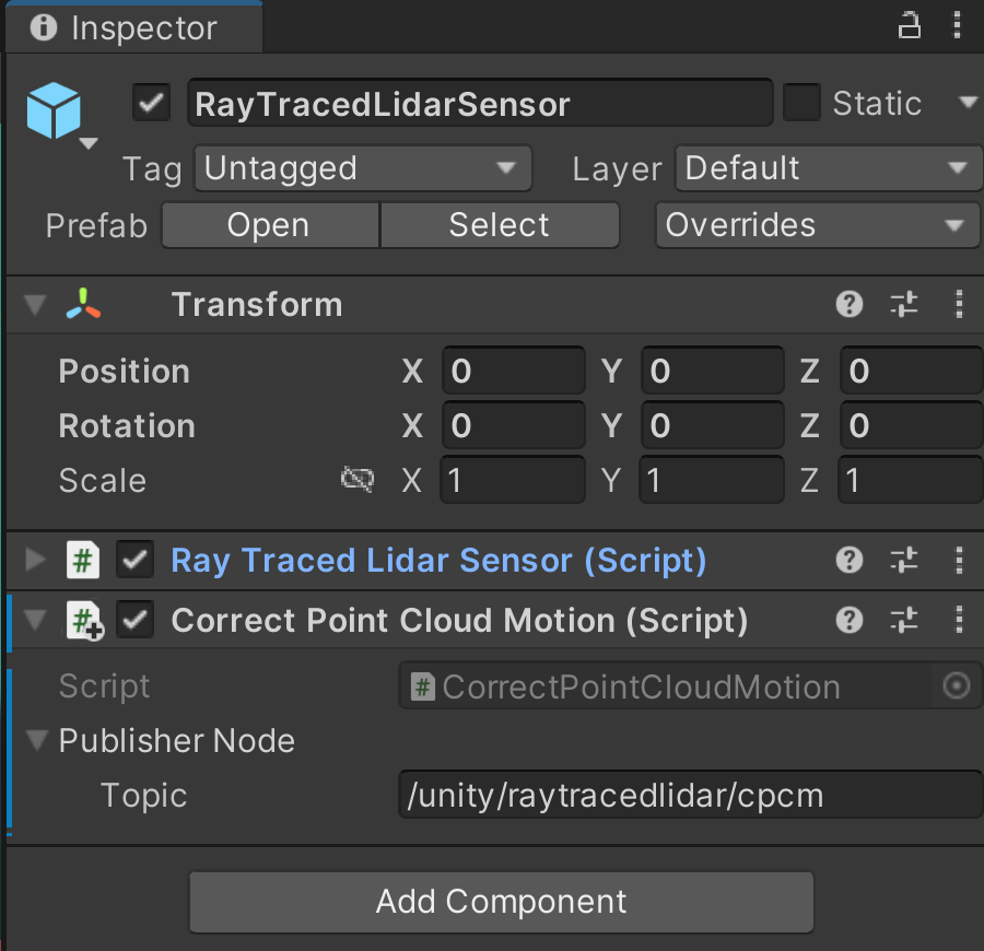
To use this component, click "Add Component" in the inspector of the GameObject that has the Raytraced Lidar Sensor. It will not work if it is not attached to the same GameObject. In the Inspector, add a topic for the corrected point cloud.
Due to thread group count limits, the CorrectPointCloudMotion component will not work for lidars that have more than 65535 total beams (Vertical Samples times Horizontal Samples) on DirectX.
Beam Divergence
For a circular beam, beam divergence is defined as the angular measure of how the beam diameter increases with the distance from the laser aperture. Simply put, it tells you how the beam grows from the source to the target.
Laser beams usually possess a Gaussian-shaped energy density distribution (or irradiance) from the center of the beam to the edges. Most of the beam energy is located at the center of the beam, along the propagation axis.
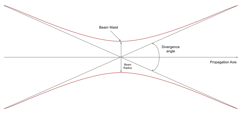
You can simulate more realistic LiDAR outputs by taking into account the laser beam width. When you set Divergence Angle to a non-zero value, the sensor will cast rays randomly inside a cone with an apex angle equal to the divergence angle, leading to noisy depth measurements. Refer to Beam divergence on Wikipedia for more information.
We now support the following algorithms to calculate the final point cloud output when beam divergence is enabled:
Random Selection: The final output for a beam is calculated based on that of a randomly chosen ray in the diverged beam. This is the default method.
Average: The final output for a beam is calculated based on the average of the output of a pre-specified number of rays in the diverged beam. This number can be set in the Samples per Beam field.
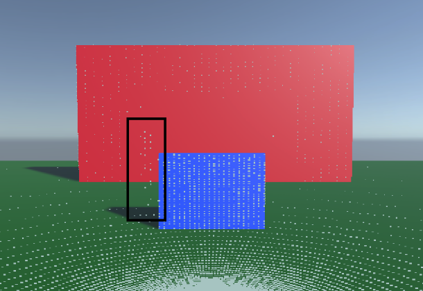
Note that a lower Samples per Beam value has better performance but at the cost of precision. In fact, this can also cause false positives to show up around the edges of some objects, which makes the LiDAR output more realistic since artifacts like these are a common problem in actual LiDARs.
Warning
Average Divergence Algorithm needs Enable Intensity to be set to
true.
