Fixing lightmap UV overlap
Each lightmapA pre-rendered texture that contains the effects of light sources on static objects in the scene. Lightmaps are overlaid on top of scene geometry to create the effect of lighting. More info
See in Glossary contains a number of charts. At run time, Unity maps these charts onto meshThe main graphics primitive of Unity. Meshes make up a large part of your 3D worlds. Unity supports triangulated or Quadrangulated polygon meshes. Nurbs, Nurms, Subdiv surfaces must be converted to polygons. Glossary contains a number of charts. At run time, Unity maps these charts onto meshThe main graphics primitive of Unity. Meshes make up a large part of your 3D worlds. Unity supports triangulated or Quadrangulated polygon meshes. Nurbs, Nurms, Subdiv surfaces must be converted to polygons. More info
See in Glossary faces, and uses the charts’ lighting data to calculate the final appearance. Because of the way GPU sampling works, data from one chart can bleed onto another if they are too close to each other. This usually leads to unintended artifacts such as aliasing, pixelation, and so on.
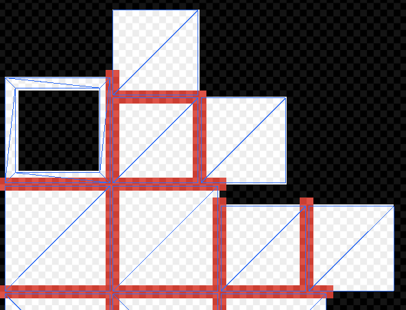
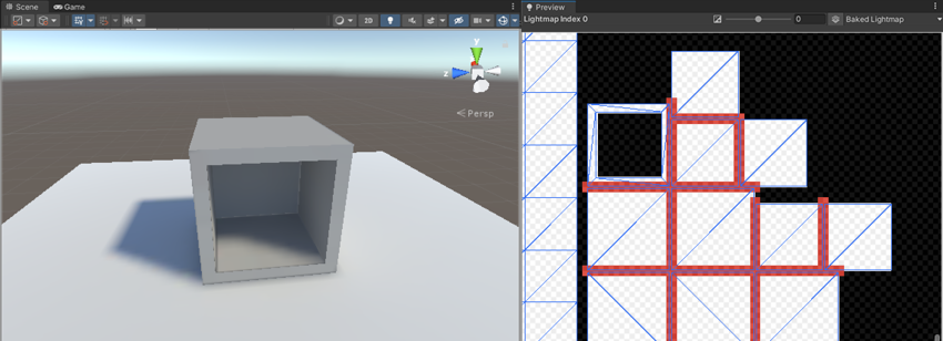
To avoid light bleeding, there must be a sufficient amount of space between charts. When a GPU samples a lightmap, the lighting system calculates the final sample value from the four texels closest to the sampled point (assuming bilinear filtering is used). These four texels are called the bilinear “neighborhood” of the sampled point. Charts are too close together if they overlap - that is, if the neighbourhood of any point inside a chart overlaps with the neighborhood of any point in another chart. In the image below, the white pixelsThe smallest unit in a computer image. Pixel size depends on your screen resolution. Pixel lighting is calculated at every screen pixel. More info
See in Glossary indicate chart neighbourhoods, and red pixels indicate overlapping neighbourhoods.
Determining optimal chart placements and spacing can be difficult, because it depends on several parameters (such as lightmap resolution, mesh UVs, and Importer settings). For this reason, Unity provides the ability to identify these issues easily, as outlined in the following section.
Identification
There are three ways to identify overlaps:
Keep an eye on Unity’s console. If Unity detects overlapping UVs, it prints a warning message with a list of affected GameObjectsThe fundamental object in Unity scenes, which can represent characters, props, scenery, cameras, waypoints, and more. A GameObject’s functionality is defined by the Components attached to it. More info
See in Glossary.Use the UV Overlap draw mode in the SceneA Scene contains the environments and menus of your game. Think of each unique Scene file as a unique level. In each Scene, you place your environments, obstacles, and decorations, essentially designing and building your game in pieces. More info
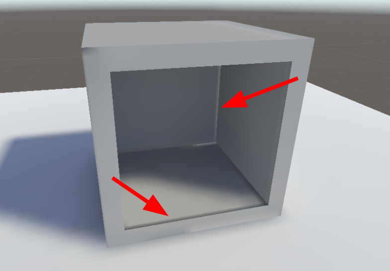
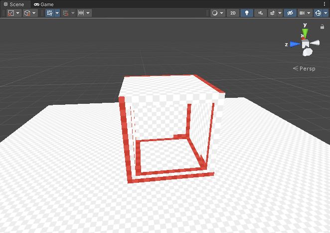
See in Glossary View (see GI visualizations in the Scene View for more information). When you have this mode enabled, Unity adds a red highlight to chart texels that are too close to texels of other charts. This is especially useful if you discover an artefact in the Scene viewAn interactive view into the world you are creating. You use the Scene View to select and position scenery, characters, cameras, lights, and all other types of Game Object. Glossary View (see GI visualizations in the Scene View for more information). When you have this mode enabled, Unity adds a red highlight to chart texels that are too close to texels of other charts. This is especially useful if you discover an artefact in the Scene viewAn interactive view into the world you are creating. You use the Scene View to select and position scenery, characters, cameras, lights, and all other types of Game Object. More info
See in Glossary, and want to quickly examine whether UV overlap is causing it.
- Use Baked Lightmaps Preview. Select a GameObject and go to the Lighting window and then choose the Baked Lightmaps tab. Double-click the highlighted lightmap, navigate to the Preview window, and select Baked UV Overlap (see dropdown in upper right corner). The Preview window colours problematic texels red in this view.
Solutions
There is no one single solution for UV overlap, because there are so many things that can cause it. Here are the most common solutions to consider:
- If you provide lightmap UVs yourself, add margins using your modelling package.
- If Unity automatically generates the lightmap UVs for a Model, you can tell Unity to increase the pack margin. The simplest way to do this is to set the Margin Method to Calculate, and set an appropriate Min Lightmap Resolution and Min Object Scale. If you prefer to set Margin Method to Manual, you can adjust the Pack Margin value directly. For more information on these settings, see documentation on Generating lightmapping UVs.
- Increase the resolution of the entire lightmap. This will increase the numbers of pixels between the charts, and therefore reduce the likelihood of bleeding. The downside is that your lightmap may become too large. You can do this in the Lighting tab under Lightmapper Settings.
- Increase the resolution of a single GameObject. This allows you to increase lightmap resolution only for GameObjects that have overlapping UVs. Though less likely, this can also increase your lightmap size. You can change a GameObject’s lightmap resolution inside its Mesh RendererA mesh component that takes the geometry from the Mesh Filter and renders it at the position defined by the object’s Transform component. More info
See in Glossary under Lightmap Settings.