Add feature vertices
Paint feature vertices by hand or use the material to add them to the branch geometry.
Paint feature vertices by hand
If you're focusing on only a few areas where you need to reveal the details of a displacement map (e.g., a low spot on the trunk), painting feature vertices by hand makes the most sense.
To paint feature vertices by hand, refer to Vertex features.
Use the material to add feature vertices
If you need to add feature vertices in many places where the displacement exists, use the material asset to assign them. The following sections detail the steps in this process.
Create and assign the heightmap
Make sure your branch map has the height map assigned. The heightmap should provide distinct pockets of high and low displacement: features that need to be emphasized with geometry.
Note
The best heightmaps for this task are often blurred versions of scanned data, hand-painted displacements, or a combination of both.
Add cutouts to the asset
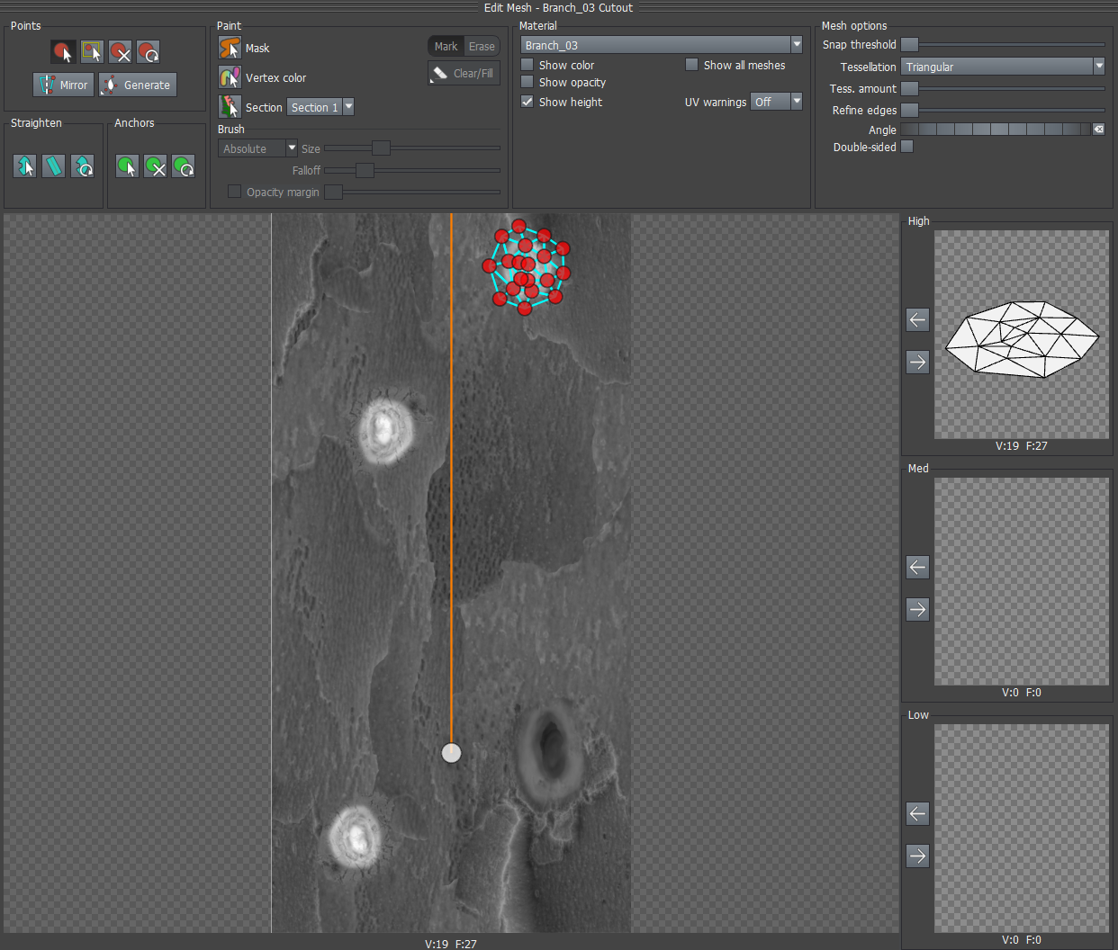
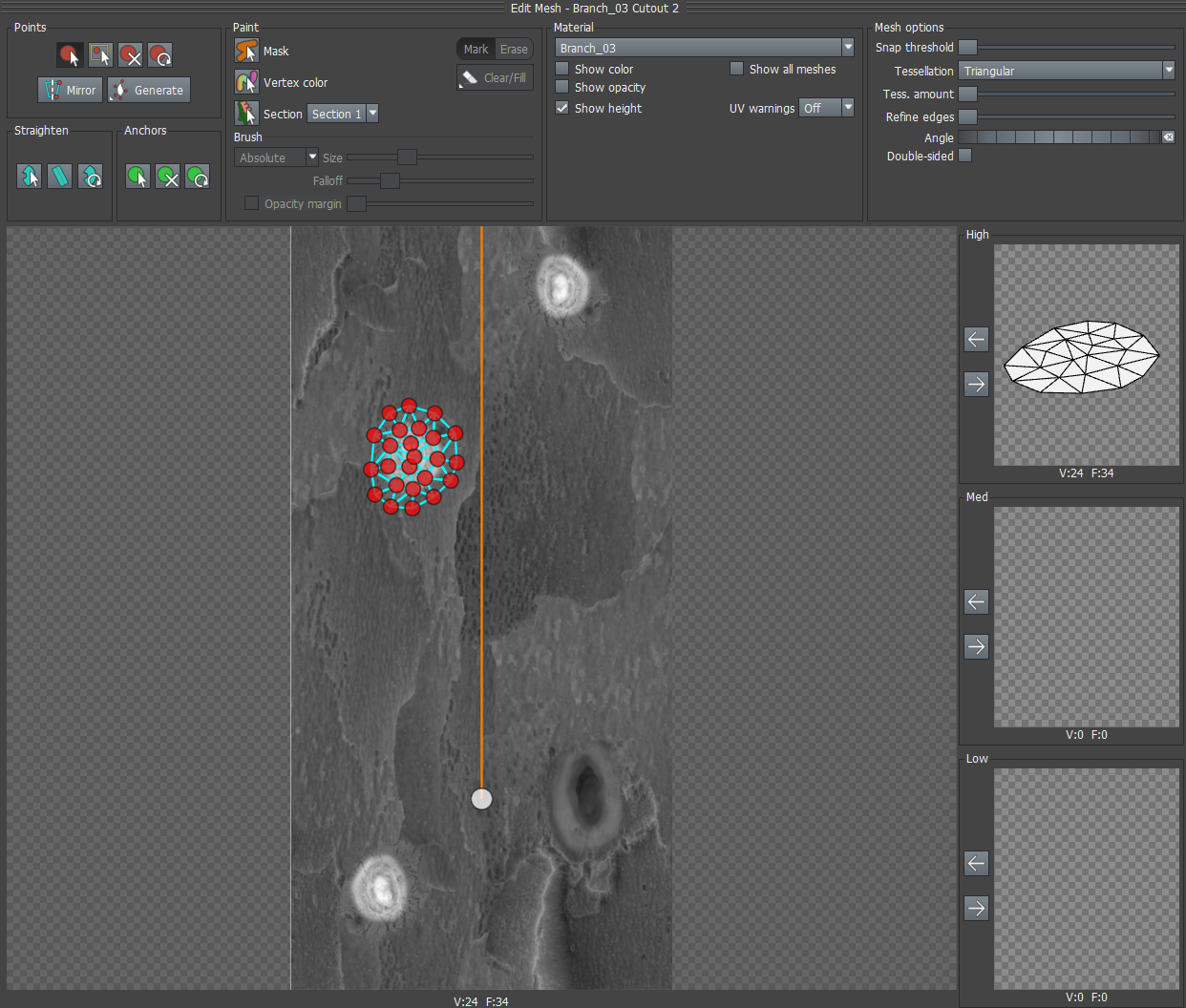
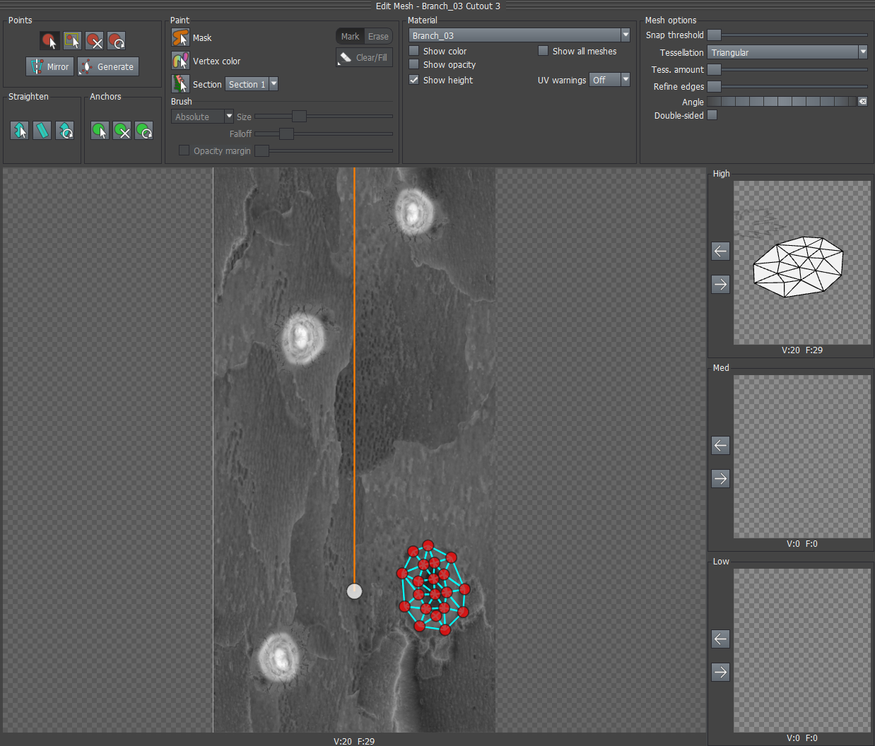
For each feature in the heightmap, add a cutout mesh to the material. Place vertices around the feature, making sure to identify the perimeter (usually low points around the feature) and the peaks (high points inside the feature). You can use the Tessellation option in the Cutout Editor to dynamically add and remove detail as necessary.
Each cutout mesh will be used on any branch that uses this material. Only the vertices will be used. The triangulation is redone by the branch as part of its computation process. The screenshots below show several feature vertex cutouts applied to an example heightmap.
Enable feature vertices on the branches
For every Branch generator that uses the material, you need to enable feature vertices in order to see them. To do this, enable the property Segments:Features:Mesh:Enabled on the Branch generators where you wish to use feature vertices.
Note
Only enable feature vertices on generators that you know will make a big difference. The polygon count will go up on these generators, sometimes significantly.
Set the displacement
The final step is to make sure the feature vertices go where you expect them to. Make sure that the Branch generator's displacement source is the material, that it's using the UV coordinates to place it, and that the U and V scales are set to 1.0. The following screenshot shows the correct Branch generator settings.
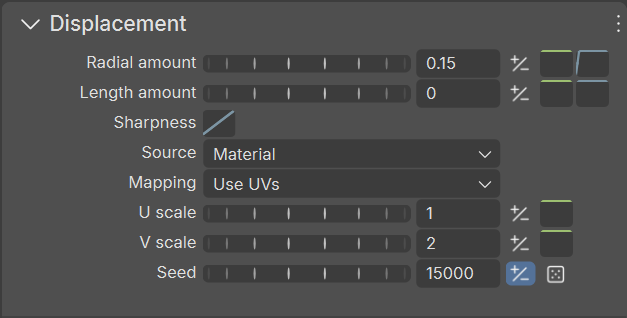
Adjust the Radial amount value until you achieve the desired look.
Best practices
Keep the following in mind when using feature vertices:
The displacement map used should be a little blurry since it will only be sampled at discrete points. Sharp edges can result in undesirable artifacts depending on where the normal vertices of the branch hit the map.
The displacement map should have small, prominent features to be called out.
Make sure you only enable feature vertices on branches that benefit substantially from them. Usually the trunk and first two levels at most.
Hand painting works well for close up shots.
Material-based features vertices work well for creating interesting branch silhouettes in midground applications.