Warning
Warning: Unity Simulation is deprecated as of December 2023, and is no longer available.
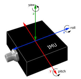
What is an IMU?
The Inertial Measurement Unit (IMU) measures orientation, angular velocity and linear acceleration in 3 dimensions (x, y, and z).
Sensor Output
All Unity sensors follow the ROS schema but are ROS-agnostic in how they serialize and send data.
The IMU outputs data in the following structure:
Schema
std_msgs/Header header
  uint32 seq
  time stamp
  string frame_id

geometry_msgs/Quaternion orientation
  float64 x
  float64 y
  float64 z
  float64 w

float64[9] orientation_covariance # Row major about x, y, z axes

geometry_msgs/Vector3 angular_velocity
  float64 x
  float64 y
  float64 z

float64[9] angular_velocity_covariance # Row major about x, y, z axes

geometry_msgs/Vector3 linear_acceleration
  float64 x
  float64 y
  float64 z

float64[9] linear_acceleration_covariance # Row major x, y z
Unity Simulation Structure
public class ImuMsg : IMessage
{
  public const string k_RosMessageName = "sensor_msgs/Imu";
  public override string RosMessageName => k_RosMessageName;

  //  This is a message to hold data from an IMU (Inertial Measurement Unit)
  //
  //  Accelerations should be in m/s^2 (not in g's), and rotational velocity should be in rad/sec
  //
  //  If the covariance of the measurement is known, it should be filled in (if all you know is the
  //  variance of each measurement, e.g. from the datasheet, just put those along the diagonal)
  //  A covariance matrix of all zeros will be interpreted as "covariance unknown", and to use the
  //  data a covariance will have to be assumed or gotten from some other source
  //
  //  If you have no estimate for one of the data elements (e.g. your IMU doesn't produce an
  //  orientation estimate), please set element 0 of the associated covariance matrix to -1
  //  If you are interpreting this message, please check for a value of -1 in the first element of each
  //  covariance matrix, and disregard the associated estimate.
  public Std.HeaderMsg header;

  public Geometry.QuaternionMsg orientation;

  public double[] orientation_covariance; //  Row major about x, y, z axes

  public Geometry.Vector3Msg angular_velocity;

  public double[] angular_velocity_covariance; //  Row major about x, y, z axes

  public Geometry.Vector3Msg linear_acceleration;

  public double[] linear_acceleration_covariance; //  Row major x, y z
}
Covariance: Covariance measures the certainty of the measurement output. In the real world, the circuit board that estimates the position and orientation is also able to output an estimate of its certainty. Usually, sudden accelerations result in more uncertainty. In our model, we simply pass the covariance data through as a static value so that downstream software can have a stand-in.
Units: The IMU output is in units/s^2 and rad/sec. The ROS schema definition specifies that the output of the acceleration by the IMU is in m/s^2 (not in g's), and that rotational velocity should be in rad/sec. Unity's simulated IMU uses the Unity scene's units, which default to meters but can be set to any user-defined unit.
Noise
Gaussian noise can be added to the output data of the IMU. This can be done by setting the mean, standard deviation, bias mean, bias standard deviation, precision, dynamic bias standard deviation, and dynamic bias correlation parameters.
Note that depending on the physics update rate, acceleration can be slightly inaccurate as physics computations and sampling happen at discrete time steps.
IMU Model
The IMU reads the angular and rotational velocity from the ArticulationBody component and calculates acceleration using delta time.
Specifically, the following properties are used
- The angular velocity is directly read from the angularVelocity field of the Articulation Body and is reported in the IMU sensor's local frame.
- The orientation, is relative to the reference pose and is read from the rotation property.
- The linear acceleration is computed by dividing the change in the velocity field of the Articulation Body component to the elapsed time.
Sensor model implications
- The output vectors are in the local coordinates of the IMU sensor and in right hand coordinate system (z is up).
- The acceleration values are in world units per seconds squared. A constant acceleration of 1G (-9.8m/s^2) toward the global upward direction is always added to the linear_acceleration vector of the IMU sensor's output. The gravity constant can be modified in the project's physics settings.
- The sensor does not read acceleration directly but rather samples velocity of the articulation body and computes acceleration, so the sensor produces a sub-sampled output.
linear_acceleration component of the IMU message. The sensor outputs ~0 m/s^2 during free fall and on the bounces, impact force creates a spike on the upward (z) axis.
linear_acceleration component of the IMU message. While the ball is rolling, the sensor outputs -1G (-9.8m/s^2) upward which changes based on the orientation of the ball. Once the ball reaches the edge and falls, linear acceleration becomes ~ 0.Properties
| Property | Function | XML Element |
|---|---|---|
| Topic | The name of the topic on which data is published. Each sensor should publish to a unique topic. | sensor/topic |
| Update Rate | The update rate in hz is the frequency at which the sensor will generate data. The IMU samples its data from the ArticulationBody and therefore can only update its data as fast as the physics engine computes a new state for the ArticulationBody. The physics engine update rate can be configured in using Fixed timestep Unity Editor's Time settings. The Fixed timestep is the interval in seconds, so the default value of 0.02 seconds means the physics engine is updated at most once every 20 milliseconds or 50 times a second. |
sensor/update_rate |
| Offset Start Time | Determines if the sensor should offset its start time by a small, random number of frames. | sensor/offset_start_time |
| Discard Redundant Data | When enabled, redundant sensor updates that have the same sensor data and time stamp will be discarded. This happens if the IMU sensor's update rate is higher than the physics update rate (controlled by fixed time step). Enabling this option will result in less message being published, so the actual update rate of the sensor will be only as high as the physics update rate. | sensor/output/discard_redundant_data |
| Noise Type | The type of noise to generate. | |
| Noise Mean | The mean of the Gaussian distribution from which additive noise values are drawn. | sensor/noise/mean |
| Noise Stddev | The standard deviation of the Gaussian distribution from which additive noise values are drawn. | sensor/noise/stddev |
Import/Export example
You can import and export Unity sensors from an XML format similar to SDF. For more details refer to Import a vehicle model: Sensors.
<sensor name="imu_sensor" type="imu">
  <update_rate>100</update_rate>
  <topic>/unity/imu</topic>
</sensor>