Warning
Warning: Unity Simulation is deprecated as of December 2023, and is no longer available.
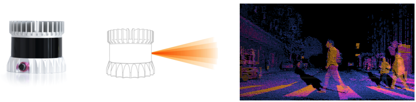
What is a LiDAR?
A Light Detection and Ranging sensor emits pulsed light waves from a laser into the environment and measures the return time to calculate the distances to surrounding objects.
We have three different LiDAR models. Each can output the same data types, but they differ in how they compute the sensor measurements from the Unity Scene. Each has its advantages and disadvantages.
- Raytraced Lidar (Recommended): Most feature-rich, most accurate, requires Windows or Linux with Vulkan
- Raster Lidar: Best for more complex scenes, can be used on Windows, Linux and macOS
- Physics Lidar: Best for machines with a good CPU but a weak GPU, can be used on Windows, Linux and macOS
Sensor Output
All LiDAR sensor types can output either laser-scan or point-cloud data. All Unity sensors follow the ROS schema but are ROS-agnostic in how they serialize and send data.
Laser-Scan Output
The laser-scan data holds a single scan from a planar laser range-finder and has the following structure:
Schemas
  Header header
    uint32 seq
    time stamp             # the acquisition time of the first ray in the scan.
    string frame_id

  float32 angle_min        # start angle of the scan [rad]
  float32 angle_max        # end angle of the scan [rad]
  float32 angle_increment  # angular distance between measurements [rad]

  float32 time_increment   # time between measurements [seconds]
  float32 scan_time        # time between scans [seconds]

  float32 range_min        # minimum range value [m]
  float32 range_max        # maximum range value [m]

  float32[] ranges         # range data [m] (values < range_min or > range_max should be discarded)
  float32[] intensities    # intensity data [device-specific units].
                           # Currently empty as we don't provide intensities yet.
Unity Simulation Structure
public class LaserScanMsg : IMessage
{
  public const string k_RosMessageName = "sensor_msgs/LaserScan";
  public override string RosMessageName => k_RosMessageName;

  //  Single scan from a planar laser range-finder
  //
  //  If you have another ranging device with different behavior (e.g. a sonar
  //  array), please find or create a different message, since applications
  //  will make fairly laser-specific assumptions about this data
  public Std.HeaderMsg header;
  //  timestamp in the header is the acquisition time of
  //  the first ray in the scan.
  //
  //  in frame frame_id, angles are measured around
  //  the positive Z axis (counterclockwise, if Z is up)
  //  with zero angle being forward along the x axis
  public float angle_min;
  //  start angle of the scan [rad]
  public float angle_max;
  //  end angle of the scan [rad]
  public float angle_increment;
  //  angular distance between measurements [rad]
  public float time_increment;
  //  time between measurements [seconds] - if your scanner
  //  is moving, this will be used in interpolating position
  //  of 3d points
  public float scan_time;
  //  time between scans [seconds]
  public float range_min;
  //  minimum range value [m]
  public float range_max;
  //  maximum range value [m]
  public float[] ranges;
  //  range data [m]
  //  (Note: values < range_min or > range_max should be discarded)
  public float[] intensities;
  //  intensity data [device-specific units].  If your
  //  device does not provide intensities, please leave
  //  the array empty.
}
Units: The range values are in Unity scene's units, which default to meters but can be set to any user-defined unit.
Ranges: The range data will contain a value for every single ray including those that did not hit. For the non-hitting rays, the value will be stored as Float.Infinity.
Noise
For each beam, an independent random noise value will be sampled from a Gaussian distribution and added to the range value.
Point-Cloud Output
The point-cloud data holds a collection of 3-dimensional points
Schema
Header header
   uint32 seq
   time stamp        # Time of sensor data acquisition
   string frame_id   # the coordinate frame ID for the 3d points

# 2D structure of the point cloud. If the cloud is unordered, height is
# 1 and width is the length of the point cloud.
uint32 height
uint32 width

PointField[] fields  # the channels and their layout in the binary data blob.

bool    is_bigendian # Is the data bigendian in this computer architecture?
uint32  point_step   # Length of a point in bytes (3x4 = 12)
uint32  row_step     # Length of a row in bytes
uint8[] data         # Actual array of 3d points [{x,y,z}]

bool is_dense        # True if there are no invalid points
Unity Simulation Structure
public class PointCloud2Msg : Message
{
  public const string k_RosMessageName = "sensor_msgs/PointCloud2";
  public override string RosMessageName => k_RosMessageName;

  //  This message holds a collection of N-dimensional points, which may
  //  contain additional information such as normals, intensity, etc. The
  //  point data is stored as a binary blob, its layout described by the
  //  contents of the "fields" array.
  //
  //  The point cloud data may be organized 2d (image-like) or 1d (unordered).
  //  Point clouds organized as 2d images may be produced by camera depth sensors
  //  such as stereo or time-of-flight.
  //  Time of sensor data acquisition, and the coordinate frame ID (for 3d points).

  public Std.HeaderMsg header;

  //  2D structure of the point cloud. If the cloud is unordered, height is
  //  1 and width is the length of the point cloud.
  public uint height;
  public uint width;

  //  Describes the channels and their layout in the binary data blob.
  public PointFieldMsg[] fields;

  public bool is_bigendian; //  Is this data bigendian?

  public uint point_step;   //  Length of a point in bytes
  public uint row_step;     //  Length of a row in bytes
  public byte[] data;       //  Actual point data, size is (row_step*height)
  public bool is_dense;     //  True if there are no invalid points
}
Units: The point coordinates are in the Unity Scene's units, which default to meters but can be set to any user-defined unit.
Fields: Layout of the data:
{string name, uint offset, byte datatype,  uint cout}
[{"x", 0, FLOAT32, 1}, {"y", 4, FLOAT32, 1}, {"z", 8, FLOAT32, 1}]
Data: Detected LiDAR hit points are serialized in a single byte array of 3D points (x, y, z).
Noise
An independent random noise value sampled from a Gaussian distribution will be added to each individual component of the hit points.
Raytraced LiDAR
The raytracing-based LiDAR uses the Vulkan Ray Tracing API directly. Rays are cast against the scene geometry. The raytracing based LiDAR has the highest accuracy of the LiDAR models, as the rays cast are intersected with the actual geometry of the objects in the scene. It's also highly efficient, as all computations are performed on the GPU.
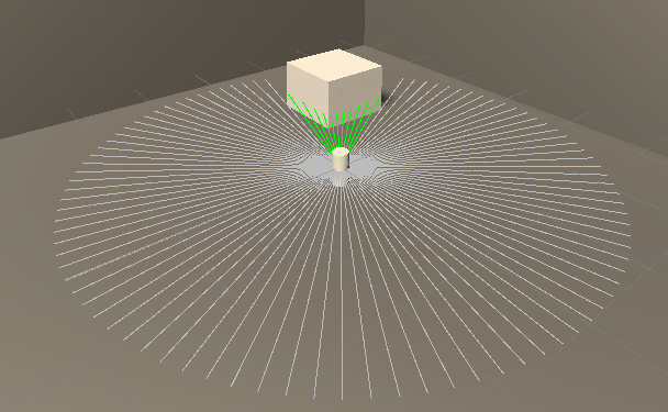
Each ray is cast from the sensor location outwards, where the detection range is determined by the sensor parameters.
Important
This LiDAR implementation works on Linux and Windows platforms.
Important
This LiDAR implementation requires a graphics card driver that supports Vulkan raytracing. Refer to the Vulkan documentation for a list of supported graphics card drivers.
The following Vulkan extensions must be supported:
- VK_EXT_descriptor_indexing
- VK_KHR_acceleration_structure
- VK_KHR_ray_tracing_pipeline
- VK_KHR_buffer_device_address
- VK_KHR_deferred_host_operations
- VK_KHR_pipeline_library
Sensor model implications
All visible geometry is packed into an acceleration structure that is used to do ray casts. The more geometry you have, the more ray intersection tests against individual triangles there will be. Thus, the computational cost increases with the Scene's visual complexity, and increases with the number of rays cast. Every simulation frame, the sensor will compute the range that the sensor should have scanned in the elapsed time and will cast any rays in that range.
In other words, the cost is mostly dictated by the scene_visual_complexity*horizontal_samples*vertical_samples*sensor_update_rate.
Additionally, when the LiDAR sampling rate is greater than the simulation rate, i.e. multiple messages are expected before Unity's Physics system has calculated changes, each LiDAR sweep will interpolate a pose between the last and current frames.
Advanced Features
We offer various advanced features for the Raytraced Lidar. These are:
- Beam Divergence
- Scan Patterns
- Custom Laser Configuration
- Point Cloud Motion Correction
- Material Spectroscopy
Properties
| Property | Function | XML Element |
|---|---|---|
| Topic | The name of the topic on which data is published. Each sensor should publish to a unique topic. | sensor/topic |
| Rotation Frequency Hz | The update rate in hz is the frequency at which the sensor will generate data, and the revolutions per second that the LiDAR spins at. |
sensor/update_rate |
| Output Type | Whether the output type is laser scan or point cloud. | sensor/output/is_laserscan |
| Is Point Cloud Organized | Specifies whether point cloud output is organized (2d-image like), or unordered. Only has effect when Output Type of the sensor is point cloud. | sensor/output/is_pointcloud_organized |
| Laser Config | A custom laser configuration asset used to define the laser distribution and firing sequence. Only available with the point cloud output type. | |
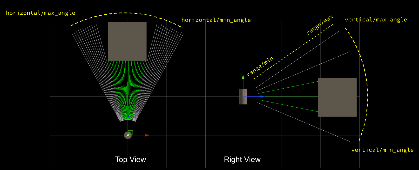
| Horizontal Samples | The number of horizontal sample steps per complete laser sweep cycle. | sensor/ray/scan/horizontal/samples |
| Horizontal Min Angle | The scan horizontal minimum angle (radians in the description file, degrees in the Unity Inspector). | sensor/ray/scan/horizontal/min_angle |
| Horizontal Max Angle | The scan horizontal maximum angle (radians in the description file, degrees in the Unity Inspector). Must be greater or equal to the Horizontal Min Angle. To configure a LiDAR that does a full circular horizontal scan, use a Horizontal Min Angle of -180 and Horizontal Max Angle of 180. |
sensor/ray/scan/horizontal/max_angle |
| Vertical Samples | The number of vertical sample steps per horizontal step. A value of 1 results in a planar LiDAR. The ray angles will be in steps of (VerticalMaxAngle - VerticalMinAngle) / (VerticalSamples - 1). |
sensor/ray/scan/vertical/samples |
| Vertical Min Angle | The scan vertical minimum angle (radians in the description file, degrees in the Unity Inspector). | sensor/ray/scan/vertical/min_angle |
| Vertical Max Angle | The scan vertical maximum angle (radians in the description file, degrees in the Unity Inspector). Must be greater or equal to the Vertical Min Angle. | sensor/ray/scan/vertical/max_angle |
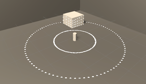
| Ray Range Min | The minimum distance for each ray. Must be less than or equal to the Ray Range Max. | sensor/ray/range/min |
| Ray Range Max | The maximum distance for each ray. Must be greater than or equal to the Ray Range Min. | sensor/ray/range/max |
| Enable Intensity | When enabled, the output point cloud will contain an intensity channel (XYZI). | sensor/ray/intensity_enabled |
| Intensity | When the "Enable Intensity" property is enabled, this value will be used for the intensity channel of the point cloud output (XYZI). | sensor/ray/intensity |
| Rotate Clockwise? | Whether the lidar rotates clockwise or counterclockwise. | sensor/ray/raytraced/rotate_cw |
| Divergence Angle | The total angular spread (apex angle) of the laser beam (radians in the description file, degrees in the Unity Inspector). This value is capped at 1 degree. Set to 0 to ignore beam divergence effects. |
sensor/ray/beam/divergence_angle |
| Focus Distance | The distance in meters along the laser beam, from the optical aperture, where the beam width is minimal. Ignored if Divergence Angle is set to 0. |
sensor/ray/beam/focus_distance |
| Divergence Algorithm | The manner in which the output point cloud data is calculated. Currently, it can be one of Random Selection or Average. Ignored if Divergence Angle is set to 0. |
sensor/ray/beam/divergence_algorithm |
| Samples Per Beam | The number of samples taken around the beam direction to measure intensity. Higher values increase quality at the cost of performance. Ignored if Divergence Angle is set to 0 or Divergence Algorithm is not set to Average. |
sensor/ray/beam/samples_per_beam |
| Wavelength | The wavelength of the laser in nanometers. | sensor/ray/beam/wavelength |
| Movement Technology | The technology used to rotate the LiDAR. Can be set to DC for a standard 360-degree LiDAR rotation, or MEMS if a custom scan pattern is desired. Only available with the point cloud output type. | sensor/movement_technology |
| Scan Pattern | The pattern that the LiDAR will rotate with when the Movement Technology is set to MEMS. Only available with the point cloud output type. |
Import/Export example
You can import and export Unity sensors from an XML format similar to the (SDF) example below:
<sensor type="raytracedlidar" name="lidar1">
  <update_rate>10</update_rate>
  <topic>/unity/lidar3</topic>
  <ray>
    <scan>
      <horizontal>
        <samples>15</samples>
        <min_angle>-1.57</min_angle>
        <max_angle>1.57</max_angle>
      </horizontal>
      <vertical>
        <samples>1</samples>
        <min_angle>-0.15</min_angle>
        <max_angle>0.15</max_angle>
      </vertical>
    </scan>
    <range>
      <min>0.05</min>
      <max>15</max>
    </range>
  </ray>
</sensor>
Limits
Points Per Second
The RayTraced LiDAR is able to run up to around 2M points per second (PPS, i.e. rotational frequency * horizontal samples * vertical samples) at 60 frames per second, depending on the machine. More points than this may significantly slow down the simulation frame rate.
Number of Meshes
The RayTraced LiDAR sensor only supports up to a maximum of 2000 unique meshes in the scene due to the Vulkan's device memory allocation limit. The exact maximum number may vary depending on the graphics card model. When the number of memory allocations is more than 90% of the maximum count, the sensor will print warnings to the Console or Logs, and you may need to consider reducing the number of unique meshes in the scene. When the number exceeds the maximum limit, it will throw Invalid Operation errors. To view the number of memory allocations from the Raytracing Service, you can go to "Simulation -> Sensors -> Export Vulkan Statistics to Console" and the memory allocation information will be logged to the console.
To reduce the number of unique meshes in the scene and keep the number under the limit, a potential approach is to combine the meshes whose relative positions and orientations are fixed into a single mesh. You can use Unity's Mesh.CombineMeshes in the script to combine meshes, mesh combination tools such as the Mesh Baker from Unity Asset Store, or 3D modeling software tools (e.g. Maya or Blender).
Mesh Components
The RayTraced lidar only interacts with the meshes in the MeshFilter and SkinnedMeshRenderer components. For the SkinnedMeshRenderer components, the lidar does not support rigging or joints, and it only uses the original static meshes instead of the dynamically skinned meshes.
To work with various poses of humanoids, for example, a potential approach is to use a static mesh for each part of the body and animate them by changing the positions and rotations of these objects. The RayTraced lidar can pick up the transformation change of the meshes and compute the ray tracing correctly.
Raster-based LiDAR
The raster-based LiDAR uses a depth buffer to capture one or more depth images from the Scene, and then samples the depth image pixels to generate the laser-scan or point-cloud data. This uses Unity's rendering engine and utilizes the GPU for both rendering the depth images and for sampling the hit points.
Sensor model implications
All visible geometry within the LiDAR's range are rendered, potentially several times per sensor update. Thus, the computational cost increases with the Scene's visual complexity, but does not increase significantly with the vertical resolution of the sensor. Every simulation frame, the sensor will compute the range that the sensor should have scanned in the elapsed time and will configure the camera frustum required to cover that range. The sensor will sweep in the elapsed time and will render the scene if there are any rays in that range. If the range required to be swept in the frame is too large then several renderings will be performed with smaller camera frustums.
In other words, the cost is mostly dictated by the scene_visual_complexity*horizontal_samples *sensor_update_rate. This makes it better for modeling sensors with a high vertical resolution.
Properties
| Property | Function | XML Element |
|---|---|---|
| Topic | The name of the topic on which data is published. Each sensor should publish to a unique topic. | sensor/topic |
| Update Rate | The update rate in hz is the frequency at which the sensor will generate data, and the revolutions per second that the LiDAR spins at. |
sensor/update_rate |
| Output Type | Whether the output type is laser scan or point cloud. | sensor/output/is_laserscan |
| Is Point Cloud Organized | Specifies whether point cloud output is organized (2d-image like), or unordered. Only has effect when Output Type of the sensor is point cloud. | sensor/output/is_pointcloud_organized |
| Horizontal Samples | The number of horizontal sample steps per complete laser sweep cycle. | sensor/ray/scan/horizontal/samples |
| Horizontal Min Angle | The scan horizontal minimum angle (radians in the description file, degrees in the Unity Inspector). | sensor/ray/scan/horizontal/min_angle |
| Horizontal Max Angle | The scan horizontal maximum angle (radians in the description file, degrees in the Unity Inspector). Must be greater or equal to the Horizontal Min Angle. To configure a LiDAR that does a full circular horizontal scan, use a Horizontal Min Angle of -180 and Horizontal Max Angle of 180. |
sensor/ray/scan/horizontal/max_angle |
| Vertical Samples | The number of vertical sample steps per horizontal step. A value of 1 results in a planar LiDAR. The ray angles will be in steps of (VerticalMaxAngle - VerticalMinAngle) / (VerticalSamples - 1). |
sensor/ray/scan/vertical/samples |
| Vertical Min Angle | The scan vertical minimum angle (radians in the description file, degrees in the Unity Inspector). | sensor/ray/scan/vertical/min_angle |
| Vertical Max Angle | The scan vertical maximum angle (radians in the description file, degrees in the Unity Inspector). Must be greater or equal to the Vertical Min Angle. | sensor/ray/scan/vertical/max_angle |
| Ray Range Min | The minimum distance for each ray. Must be at least greater than or equal to the near-clip plane of the sensor's camera and less than or equal to the Ray Range Max. | sensor/ray/range/min |
| Ray Range Max | The maximum distance for each ray. Must be at least greater than or equal to the Ray Range Min and less than or equal to the far-clip plane of the sensor's camera. | sensor/ray/range/max |
| Enable Intensity | When enabled, the output point cloud will contain an intensity channel (XYZI). | sensor/ray/intensity_enabled |
| Intensity | When the "Enable Intensity" property is enabled, this constant value will be used for the intensity channel of the point cloud output (XYZI). | sensor/ray/intensity |
| Noise Type | The type of noise to generate. | |
| Noise Mean | The mean of the Gaussian distribution from which additive noise values are drawn. | sensor/noise/mean |
| Noise Stddev | The standard deviation of the Gaussian distribution from which additive noise values are drawn. | sensor/noise/stddev |
| Texture Width | The width of the texture used to capture the depth image. Larger width improves the sampling accuracy at the cost of performance and GPU memory. | sensor/ray/raster/texture_width |
| Texture Height | The height of the texture used to capture the depth image. Larger hieght improves the sampling accuracy at the cost of performance and GPU memory. | sensor/ray/raster/texture_height |
| Maximum Angle Per Render | The maximum field of view that the depth camera can have for each rendering of the scene. If the range required to be swept in the frame is larger than the Maximum Angle Per Render, then several renderings will be performed with smaller camera frustums. Use smaller value for better scan quality and larger value for better performance. | sensor/ray/raster/scan/horizontal/max_fov |
| Maximum Delta Time Per Update | Maximum delta time (seconds) allowed for a single update. Deltas larger than this will be clamped to this value. | sensor/ray/raster/max_delta_time |
Parameter tuning: Performance vs. Quality
You may need to tweak some parameter values when setting sensor parameters based on an actual LiDAR sensor's specifications. For certain parameters like update rate and number of vertical and horizontal samples, the exact numbers from the real sensor specifications can be used as is. Quality parameters like max_fov, texture_width and texture_height on the other hand are used to balance between computational performance and quality.
The faster the LiDAR sweeps the horizontal range, the bigger angles it renders, and the bigger the angle, the more the error gets as objects move away from the camera's forward direction. You can reduce the error by limiting the max_fov to make the LiDAR's sweeping shape from a polygonal into a more circular shape. But it comes at a cost of requiring to perform more renders per frame. The horizontal sweep requires a large texture width, especially when the angle being rendered is large. However the texture height is less sensitive, especially with few vertical beams. We suggest having at least 1 pixel in texture height per vertical beam.
Example: For a single beam (planar) LiDAR operating at a low update rate on a high frame-rate simulation, even a small 2x2 texture can be enough.
Import/Export example
You can import and export Unity sensors from an XML format similar to the (SDF) example below:
<sensor type="rasterlidar" name="lidar2">
  <update_rate>10</update_rate>
  <topic>/unity/lidar2</topic>
  <ray>
    <scan>
      <horizontal>
        <samples>15</samples>
        <resolution>1</resolution>
        <min_angle>-1.57</min_angle>
        <max_angle>1.57</max_angle>
      </horizontal>
      <vertical>
        <samples>1</samples>
        <resolution>1</resolution>
        <min_angle>-0.15</min_angle>
        <max_angle>0.15</max_angle>
      </vertical>
    </scan>
    <range>
      <min>0.05</min>
      <max>15</max>
      <resolution>0</resolution>
    </range>
    <raster>
      <max_fov>90</max_fov>
      <texture_width>32</texture_width>
      <texture_height>32</texture_height>
    </raster>
  </ray>
</sensor>
Physics-based LiDAR
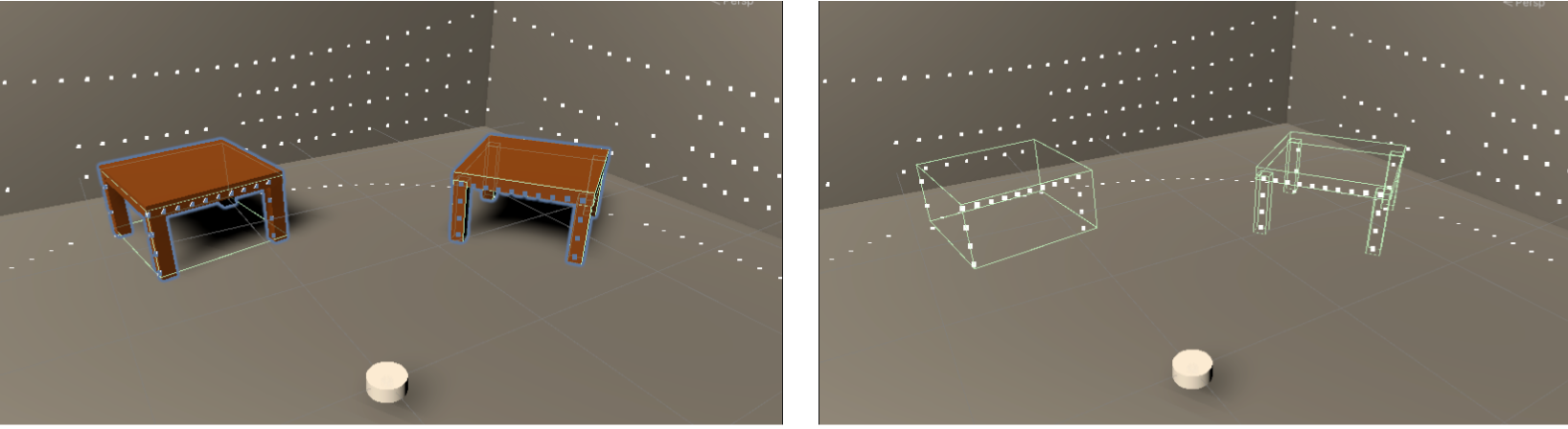
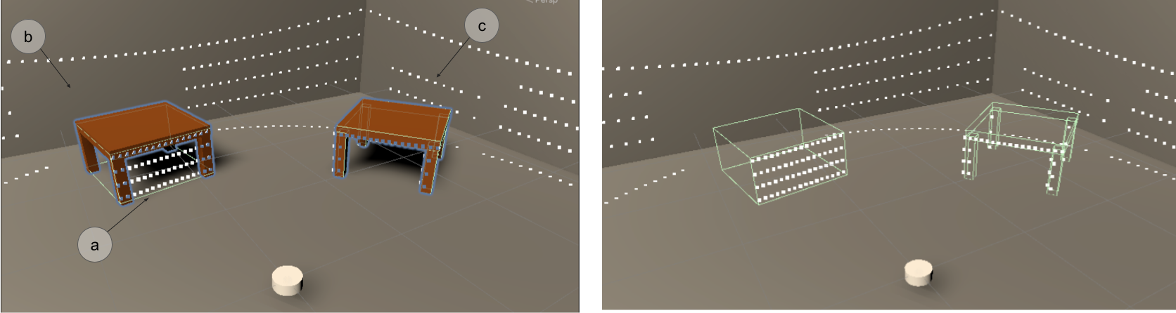
The physics-based LiDAR uses Unity's physics engine. Rays are cast against all physics colliders in the Scene, so only objects that have physics colliders will be detected. Note that the geometry observed from physics ray-casting will match the colliders' geometry, as opposed to the visual rendered geometry.
Each ray is cast from the sensor location outwards, where the detection range is determined by the sensor parameters.
Sensor model implications
The ray intersection computations are performed on the CPU, and the computational cost of each ray cast increases proportionally with the complexity of the Scene's physics geometry. The computational cost is proportional to number_of_scene_colliders x number_of_rays x sensor_update_rate. So the performance may suffer in complex scenes with many complex collision geometry, with sensor configured to have high update rate and many rays cast per update (horizontal_samples x vertical_samples).
Properties
| Property | Function | XML Element |
|---|---|---|
| Topic | The name of the topic on which data is published. Each sensor should publish to a unique topic. | sensor/topic |
| Update Rate | The update rate in hz is the frequency at which the sensor will generate data, and the revolutions per second that the LiDAR spins at. |
sensor/update_rate |
| Output Type | Whether the output type is laser scan or point cloud. | sensor/output/is_laserscan |
| Is Point Cloud Organized | Specifies whether point cloud output is organized (2d-image like), or unordered. Only has effect when Output Type of the sensor is point cloud. | sensor/output/is_pointcloud_organized |
| Horizontal Samples | The number of horizontal sample steps per complete laser sweep cycle. | sensor/ray/scan/horizontal/samples |
| Horizontal Resolution | This number is multiplied by the Horizontal Samples to determine the number of range data points returned. If resolution is less than 1, range data is interpolated. If resolution is greater than 1, range data is averaged. The default is 1. |
sensor/ray/scan/horizontal/resolution |
| Horizontal Min Angle | The scan horizontal minimum angle (radians in the description file, degrees in the Unity Inspector). | sensor/ray/scan/horizontal/min_angle |
| Horizontal Max Angle | The scan horizontal maximum angle (radians in the description file, degrees in the Unity Inspector). Must be greater or equal to the Horizontal Min Angle. To configure a LiDAR that does a full circular horizontal scan, use a Horizontal Min Angle of -180 and Horizontal Max Angle of 180. |
sensor/ray/scan/horizontal/max_angle |
| Vertical Samples | The number of vertical sample steps per horizontal step. A value of 1 results in a planar LiDAR. The ray angles will be in steps of (VerticalMaxAngle - VerticalMinAngle) / (VerticalSamples - 1). |
sensor/ray/scan/vertical/samples |
| Vertical Resolution | This number is multiplied by the Vertical Samples to determine the number of range data points returned. If resolution is less than 1, range data is interpolated. If resolution is greater than 1, range data is averaged. The default is 1. |
sensor/ray/scan/horizontal/resolution |
| Vertical Min Angle | The scan vertical minimum angle (radians in the description file, degrees in the Unity Inspector). | sensor/ray/scan/vertical/min_angle |
| Vertical Max Angle | The scan vertical maximum angle (radians in the description file, degrees in the Unity Inspector). Must be greater or equal to the Vertical Min Angle. | sensor/ray/scan/vertical/max_angle |
| Ray Range Min | The minimum distance for each ray. | sensor/ray/range/min |
| Ray Range Max | The maximum distance for each ray. | sensor/ray/range/max |
| Enable Intensity | When enabled, the output point cloud will contain an intensity channel (XYZI). | sensor/ray/intensity_enabled |
| Intensity | When the "Enable Intensity" property is enabled, this constant value will be used for the intensity channel of the point cloud output (XYZI). | sensor/ray/intensity |
| Noise Type | The type of noise to generate. | |
| Noise Mean | The mean of the Gaussian distribution from which additive noise values are drawn. | sensor/noise/mean |
| Noise Stddev | The standard deviation of the Gaussian distribution from which additive noise values are drawn. | sensor/noise/stddev |
| Is Progressive | When disabled, all ray casts will happen at the same frame. Otherwise they will be progressively cast in multiple frames (based on the framerate of the simulation and update rate of the sensor). | sensor/ray/scan/is_progressive |
| Range Resolution | Linear resolution of each ray. default is 0. |
sensor/ray/range/resolution |
vertical samples = 6 and horizontal samples = 50.Import/Export example
You can import and export Unity sensors from an XML format similar to the (SDF) example below:
<sensor type="ray" name="lidar3">
  <update_rate>10</update_rate>
  <topic>/unity/lidar1</topic>
  <ray>
    <scan>
      <horizontal>
        <samples>15</samples>
        <resolution>1</resolution>
        <min_angle>-1.57</min_angle>
        <max_angle>1.57</max_angle>
      </horizontal>
      <vertical>
        <samples>1</samples>
        <resolution>1</resolution>
        <min_angle>-0.15</min_angle>
        <max_angle>0.15</max_angle>
      </vertical>
    </scan>
    <range>
      <min>0.05</min>
      <max>15</max>
      <resolution>0</resolution>
    </range>
  </ray>
</sensor>
This will model a 10hz planar LiDAR that casts rays in 15 steps from -1.57 to 1.57 radians (-90 to +90 degrees), with a detection range in [0.05, 15].