Warning
Warning: Unity Simulation is deprecated as of December 2023, and is no longer available.
Calibrate a camera
You can use the camera calibration scene from the Simulation Sensors package samples to capture images of calibration grids. You can then use these images to calibrate your sensor, using third-party software like OpenCV.
Import the camera calibration scene
Import the Advanced samples to add the camera calibration scene and necessary assets to your project. To open the scene, navigate to:
Assets\Samples\Simulation Sensors\[version]\Advanced\CameraCalibration\CameraCalibration.unity
Set the save path
The calibration scene saves multiple files to disk during Play Mode. Before entering Play Mode, you can specify a folder where the files are saved:
- In the Hierarchy window, select the Calibrator GameObject.
- In the Inspector window, set Save Path to the desired folder. You can right-click and select Browse... to choose the folder interactively.

Play the calibration scene
When you enter Play Mode in the camera calibration scene, the following happens:
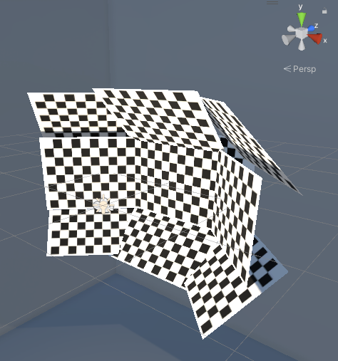
- All GameObjects under Calibrator are assumed to be calibration grids.
- Calibration grid GameObjects are enabled one at a time.
- An image is read from the specified image topic and saved as a PNG file, for each grid. The file name matches the GameObject name.
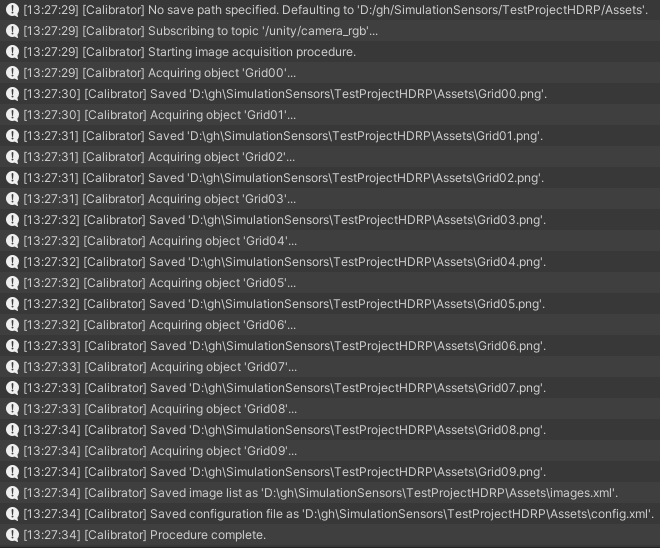
- Two XML files are generated in the format expected by OpenCV's camera calibration C++ sample.
After a successful run, you should see a similar output in the Console Window:
Calibrate the camera using OpenCV
You can use OpenCV to estimate the camera parameters using the grid images generated by the camera calibration scene.
Install OpenCV according to your platform. The camera calibration scene has been tested with OpenCV 4.5.4.
Locate the camera calibration C++ sample on GitHub or in the OpenCV source files, under:
sources\samples\cpp\tutorial_code\calib3d\camera_calibration\camera_calibration.cppCompile the C++ file into a new project that links with OpenCV libraries. Follow the instructions for your IDE and platform.
Run the program with the full path to the
config.xmlfile generated by the camera calibration scene as single command-line argument.Select the image window and press a key to cycle through all the images.
The program outputs the results in output.xml, next to config.xml. You can find the camera principal point and focal length under camera_matrix, and the distortion parameters under distortion_coefficients.
Note
The definition for the distortion coefficients depends on whether the fisheye lens model or the regular lens model is used. Select the appropriate model using the Use Fisheye Model property of the Calibrator component on the Calibrator GameObject.
Note
The translation vector of each grid as logged in the extrinsic_parameters section of output.xml is expressed as a multiple of the chessboard grid square size instead of in meters.
Customize the scene
You can customize the camera calibration scene in multiple ways.
Use a different sensor
By default, the camera calibration scene uses the fisheye camera sensor located under the CameraBase GameObject. You can change it for another sensor that publishes image messages, like the regular RGB camera Prefab.
After changing the sensor Prefab, you might also need to update the scene further:
- Ensure the image topic the sensor publishes to matches the topic the Calibrator listens to. By default, the topic is named
/unity/camera_rgb. - Move the grid GameObjects to cover the sensor field of view.
- Configure the Use Fisheye Model property of the Calibrator according to the lens model used by the sensor.
Change the number of grids and their position
In the aggregate, the calibration grids should span as much of the sensor field of view as possible, in as many different orientations as possible. Also, each grid should be entirely visible to the sensor.
To position a grid in the sensor field of view:
- Enter Play Mode and wait for the calibration procedure to complete.
- In the Game view, in the Visualization HUD, select Topics, then
/unity/camera_rgbto see a preview of the sensor image. - Select the grid GameObject to reposition, under Calibrator in the Hierarchy window.
- Enable the GameObject and use either the Inspector or the Scene view to move and rotate the grid.
Copy the Transform component.

Exit Play Mode.
Paste the Transform component values.

To add more grids, you can duplicate an existing grid GameObject. Rename the GameObject, as the name is also used as file name for the grid image.
Note
All GameObjects that are children of the Calibrator GameObject are assumed to be calibration grids. Whether the GameObject is enabled or disabled at the start of Play Mode has no effect on whether the grid is used.
Provide your own calibration grid image
If you use your own grid image, for example with a different number of grid squares, you must do the following:
- To ensure the grid is made of squares, set the aspect ratio of the grid GameObject to be the same as the aspect ratio of the grid image. For plane GameObjects, this means the ratio of Scale X and Z components must match the ratio of the grid image width and height.
- Set the Grid Width and Grid Height properties of the Calibrator. You must use the number of inner intersections, which correspond to the number of squares minus one.
- If you use something else than a chessboard, like a grid of circles, set the Calibration Pattern of the Calibrator.
Configure the calibrator
Select the Calibrator GameObject to set the properties of the Calibrator component in the Inspector.
| Property | Description |
|---|---|
| Save Path | The path used to save image files. If left empty, defaults to the project Assets directory. Right-click to browse. |
| Camera Topic | The topic used by the camera to calibrate. |
| Calibration Pattern | The type of calibration pattern used. |
| Grid Width | The number of inner intersections per row. The minimum is 2. |
| Grid Height | The number of inner intersections per column. The minimum is 2. |
| Use Fisheye Model | Whether to request using a fisheye lens model during calibration. |