Warning
Warning: Unity Simulation is deprecated as of December 2023, and is no longer available.
Manually create a vehicle model
To create a model we need to ensure the Unity simulation has:
- Visual geometry, which defines how the object looks and is interpreted by the rendering pipeline.
- Articulation bodies, which define how the parts move with respect to each other (e.g. revolute or prismatic constraint) as well as the object's mass.
- Collision geometry, which defines how objects contact each other.
Geometry creation
We can create geometry in one of two ways:
- Import a 3D mesh. This is good if you have an external tool you use or want to use to create the geometry.
- Create primitives. This is good for simple shapes and primitives that you want to experiment quickly with.
Geometry creation method 1: Import
Unity has many built-in importers. If you have SolidWorks files or similar and can export them as .fbx, .dae (Collada), .dxf, or .obj; you can then import them directly into Unity with their geometry and material. Simply copy the mesh files (geometry, textures, etc.) into your Unity project's Assets directory (or a sub-directory).
Geometry creation method 2: Create via the Editor
You also have the option to create geometry in the Unity Editor.
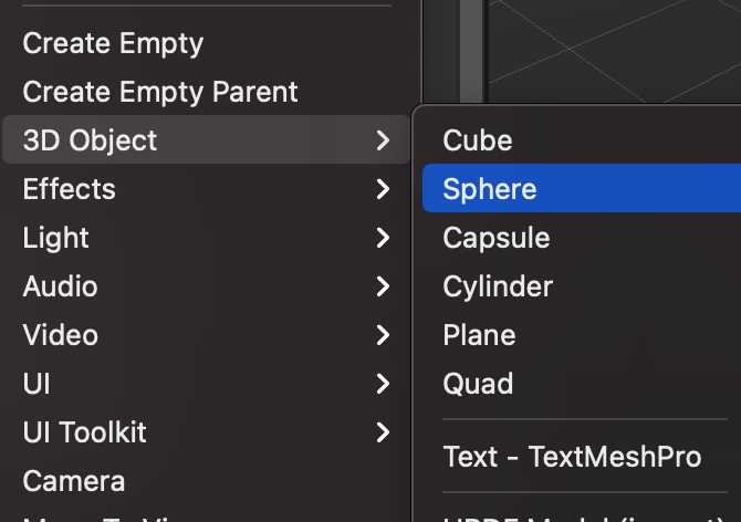
- Right-click on the project hierarchy -> 3D Object
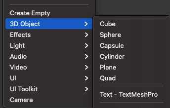
Then select any of the basic shapes that you want to use approximate your robot. It will probably mostly consist of cubes, cylinders and spheres.

When prototyping your robot this way, we recommend separating the collision and visual GameObjects from the GameObject that will have the ArticulationBody component. You can do that by just having the colliders and visual components belong to a child of the GameObject that contains the ArticulationBody component. This way you will have more control over where your vehicle parts are in relation to their connecting joints and also possibly avoid shearing behavior when using ArticulationBodies with Transforms that are not uniformly scaled. That might cause incorrect physics simulation results.
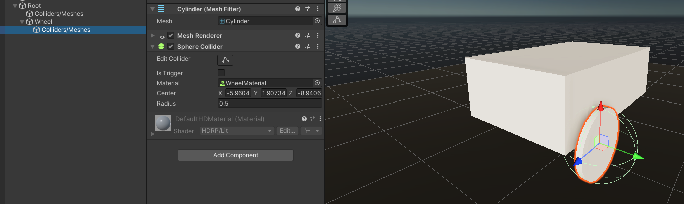
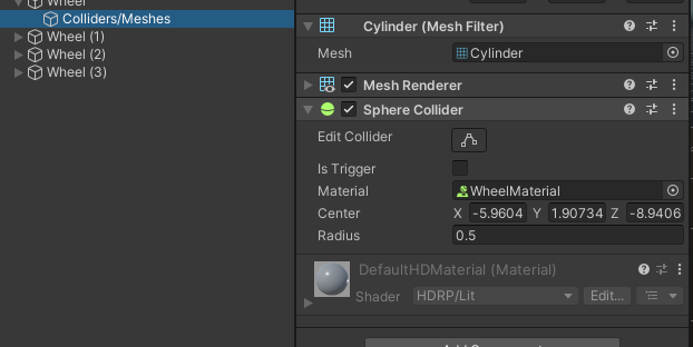
An important note to keep in mind if your robot has wheels: you may use cylinder shapes to approximate your wheels, but we recommend replacing their MeshCollider component with a Sphere Collider for better physics simulation results when driving the robot.
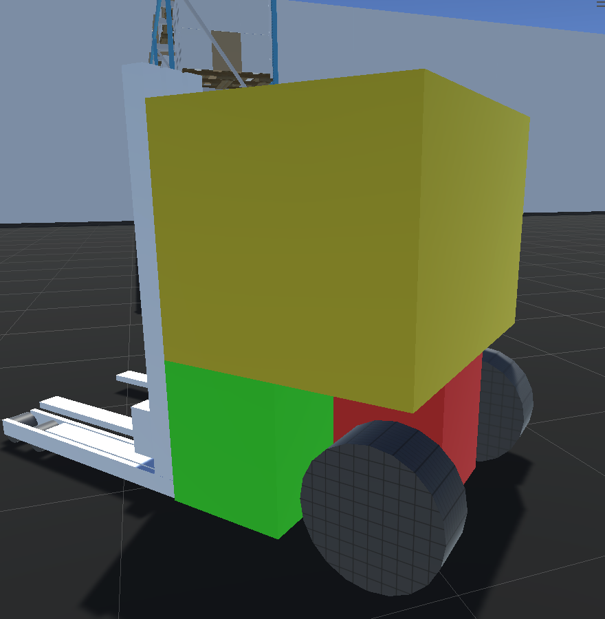
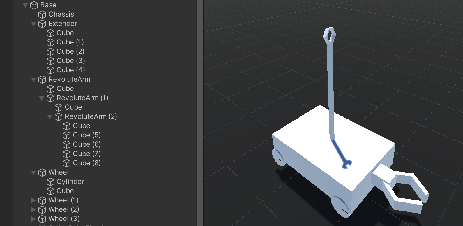
Your robot could eventually look something like this:

(optional) Add materials to modify the model appearance
You can optionally add or modify the model materials by assigning a material asset to the GameObject. You can select or tune a set of default colors in the inspector or use one of the thousands of free materials in the Unity Asset Store. For more information on Unity materials, check out the reference documentation.

The reason this point is optional is that the physics simulation does not use the visual components in its calculations. The MeshFilter, MeshRenderer, and any other purely visual components are only meant for human readability when working with the system. If the intent is to run these robots in headless mode (meaning there would be no Editor interface and commands would be passed via the Command Line Interface), then these visual components can be ignored and removed, unless someone will be investigating visual capture data at a later point.
Add physical properties
Now that we have a visual vehicle model with all the colliders attached, we need to add the components that will actually drive the interactions between them. This is what ArticulationBody components are for!
An ArticulationBody component is meant to be used in a chain of bodies and defines how each link will be able to move in relation to its parent. The ArticulationBody component encompasses the physical body properties like mass and also the properties of the joint that connects to its parent. Each piece of your robot that will be moving or has separate body properties needs to have an ArticulationBody component.
Based on the vehicle you'll be creating, you will be choosing out of four possible joint types:
- Fixed. This is a joint that has no degrees of freedom and is an equivalent of welding the two pieces together.

- Prismatic. This joint type allows for one linear degree of freedom. It's practically a slider along a specified axis relative to the parent anchor.
- Revolute. This joint type allows for one angular degree of freedom. A revolute joint is essentially a hinge with a single rotational degree of freedom around the parent anchor’s X axis. It should be used for anything that might rotate in relation to the parent body.
- Spherical. The spherical joint provides up to three degrees of freedom. Think of a ball-and-socket joint, where the joint allows movement on three axes.
Warning
Spherical Joints
While it is convenient and tempting to use the spherical type for some joints, we recommend splitting each axis of freedom into a separate revolute joint. Spherical joints in PhysX tend to have a lot of instability when it comes to solving all the constraints. If you have a joint that has more than one DoF, decompose that joint into separate ArticulationBodies per each degree of freedom - one revolute joint for motion along the X axis, one for the Y axis and so on.
Add ArticulationBody components
To create an ArticulationBody chain all you need to do is add the ArticulationBody component to a GameObject. This will serve as the root of your articulation tree. Put the next GameObject with the ArticulationBody component as a child of the first one and so on, based on how many joints has and what movements your robot is capable of.
If some parts do not need to be moved in relation to each other, instead of placing each of them with a fixed joint, you can put them all under one ArticulationBody with individual colliders.
For example, you could have a body that is made up of lots of small bits and pieces, but for the simulation, you can just approximate the chassis with one ArticulationBody component if it doesn't have any specific motions that it needs to be able to do.
Adjust ArticulationBody properties as per your robot model
The full explanation for each property can be found in the Articulation Body Manual and the Articulation Body Scripting reference.
💡 Units of Measurement
You can find the units of measurement used by every ArticulationBody or ArticulationDrive property in our scripting reference!
Anchor Joint Limits Tool and Anchor Transform Tool
Don't forget to make use of the Anchor Joint Limits and Anchor Transform tools! They will help you orient the anchors of your ArticulationBody components!

- Anchor joint limit tool - This tool shows you the current rotation axis and the rotation limits in case the axis is set to Limited. Click and drag on the handles to change the upper and lower limits.

- Anchor transform tool - This tool shows you the anchor position and rotation. Click and drag on the relevant gizmo arms, just like with classic Unity Transforms.
![]()
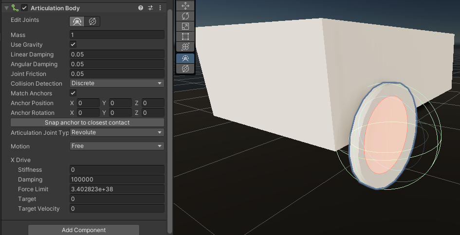
Let's take a look at the ArticulationBody components.
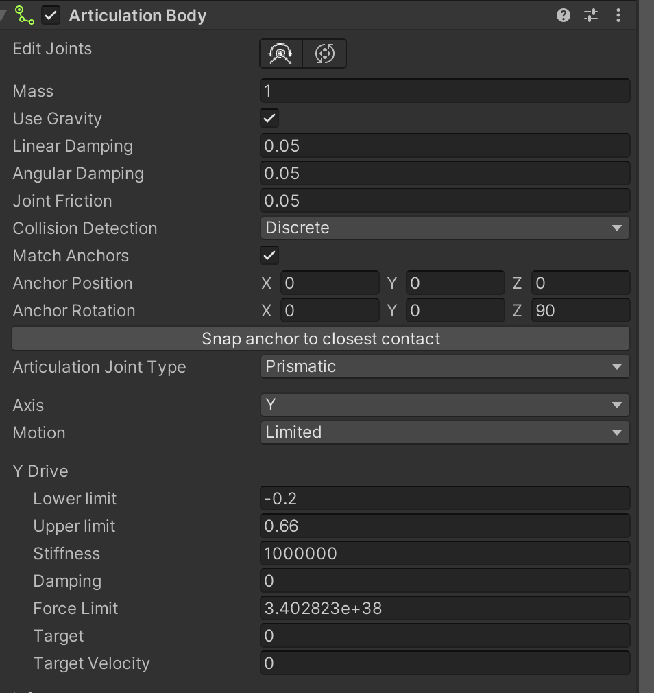
- Damping and friction defines how much energy fall-off is simulated for the entire ArticulationBody. It's good to have at least a little bit, so that your joints don't enter a scenario where they will never stop and keep the whole chain awake, introducing minor errors in the simulation. These are coefficient properties without any units of measurement.
- Anchor position/rotation defines where and what rotation the anchor is, which will change the starting point and direction of your joint's motion.
- Match Anchors will make sure the joint anchor and the parent anchor are positioned the same, which is the preferred setup most of the time; if you need to, you can disable this and modify the joint anchor and joint parent anchor properties independently of each other.
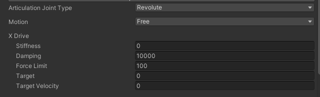
- Everything from the Articulation Joint Type and below will define your Articulation Drives; each drive defines one degree of freedom on a body, its properties, and any available constraints. Fixed joints will have 0 drives, Revolute and Prismatic will have 1 drive, and Spherical will have up to 3. This is what drives the joints to reach a specific target or reach a target velocity. Each drive has a set of properties that define how the joint will be propelled, what limits it should have and how fast it should move.
Articulation Drive parameters
- Lower and Upper Limits - these will define how far the joint cant extend/rotate before being clamped. This is how you define the lower and upper ranges for your joint movement. These will only show up if you set the Motion dropdown to Limited.
To talk about stiffness, damping or the target properties, we first need to take a look at the formula that their effect is calculated into:
Effect = stiffness * (drivePosition - targetPosition) - damping * (driveVelocity - targetVelocity)
As you can see stiffness and target position are linked the same way as damping and target velocity are.
- Stiffness - How strongly the spring will try to reach the position Target.
Damping - How strongly the spring will try to reach the TargetVelocity.
Force Limit - This is the upper boundary for the force that should be applied to the ArticulationDrive. This effectively clamps the output of the above Effect formula to the specified value.
💡 From our documentation
Notice that the effect formula consists of two independent terms that you can balance, and even cancel out. For example:
If you set the stiffness to zero, you get a drive that only aims at reaching a specific velocity.
If you set the damping to zero, you get a drive that aims at reaching a certain position without trying to reach any particular velocity. In that case, the drive does not try to eventually stop once the target is reached.
Add colliders
Colliders are the main way to give your objects a shape in the physics simulation. They will consist of basic shapes like Box, Sphere, or Capsule, or they can be more complex shapes like a mesh collider (more computationally expensive). It is common to approximate the colliders using basic shapes to use less processing time, but if there is a need for a more detailed model, mesh colliders are fine as well.
To add a collider to a GameObject, just add the relevant Collider component to it (BoxCollider or SphereCollider, etc.) If you are creating basic shapes from the Hierarchy context menu (right-click somewhere in the hierarchy -> 3D Objects) menu, the colliders will already be attached.
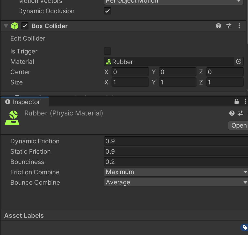
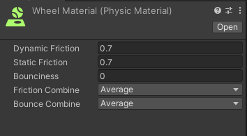
Each collider has a friction material associated with it. If you want your wheels to have more friction like rubber or be more slippery as if they were made of ice, you can adjust those with a Physic Material object. All values are in the range of [0, 1] , where 0 will be completely frictionless and 1 will produce maximum friction.

Note: When importing the robots from a URDF, there is an option to use VHACD, which will deconstruct your complex meshes and will try to create a simpler mesh for collisions.
You should be able to prototype most forms of robotic vehicles with this method.
Recap
So, let's go over the steps we just learned to create a robot from scratch!
1. Create the hierarchy of GameObjects for each ArticulationBody component
You don't have to create the entire hierarchy, but as mentioned before, it is best to keep the ArticulationBody on the parent GameObject and then add the Geometry and Collision components on a child GameObject. So each time you want to add an ArticulationBody, you should follow this structure.

2. Add geometry and colliders by either using built-in shapes or importing them from 3rd party software
In this case we are using sphere colliders for the wheels.
3. Add ArticulationBody components

4. Adjust ArticulationBody parameters to fit your robot.
Adjust the parameters so that it makes sense for your robot. In this case, it's a wheel with a revolute joint oriented and positioned so that it would support the main body and be able to roll forward/backward.
5. Define Physical properties of your wheels
Create a PhysicMaterial and define the friction settings that you want. Usually it will be more friction for driving wheels and little to no friction for caster wheels if your robot has them.
6. Add controller stack
And finally, add the controller that makes sense for your robot from our controller stack. We will be going into more depth about the controller stack in another section, but for now, in this example the robot has a differential drive controller attached and the wheels defined in the Wheel Pairs field.

Congratulations! You should now be able to move your robot by pressing the W A S D keys. We will be looking at each controller type and the related components in the Control a Vehicle Model section.