Warning
Warning: Unity Simulation is deprecated as of December 2023, and is no longer available.
Modifying simulation parameters
It is likely that for your specific robot you will need to adjust some ArticulationBody component or vehicle configuration parameters so that the simulation better matches your real life robot. If you are not using our Authoring scripts, you will have to adjust these values manually or create a script of your own! Here we will be going over some properties that you can modify to achieve a more desirable simulation.
General vehicle setup tips
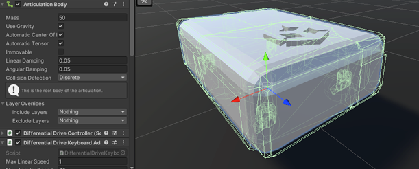
- Mass - Measured in kilograms, this property should try and match your real life robot as much as possible. Although, sometimes modifying some of the bodies in your robot chain should be expected. Having a larger mass on your driving wheels should help the robot reach its target velocities better, while having a smaller mass on your caster wheels limits their possible negative effect on reaching those velocities. Also, a correct mass configuration should help with issues like your robot tipping over. Take note, that you can set the Center of Mass in the local space for each Articulation Body component through the scripting API (and through the inspector since 2022.2.0a8) So for example a vector of (0, 0, 0) would mean the center of the body.
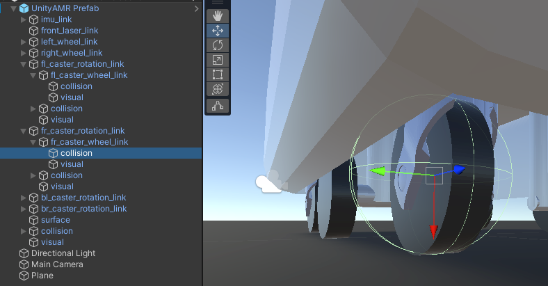
- Sphere colliders for wheels - We've mentioned this in their separate pages, but it's worth re-iterating that currently, for best results, your wheels should have a sphere collider on them. While MeshColliders can be pretty detailed, they will still be inferior to the simple shape of the sphere. For example, the sphere would produce less jiterry results while moving the vehicle around when compared to a MeshCollider cylinder wheel.
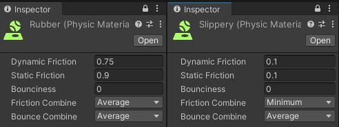
- Physic Materials - Physic Materials are assets that define a collider's friction and bounce terms. These are important, since your basic means of locomotion will depend on your wheel's friction. For the driving wheels we recommend setting something with a higher friction, while for the caster wheels something almost entirely frictionless. The Friction Combine property defines how the total friction effect is calculated, since every collision will be a result of a pair of colliders interacting, both of which could have different physic materials.
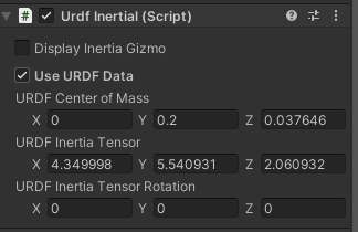
- SDF Imported settings - The vehicle description file may have parameters like Inertia tensors that come with it. While they are not inherently wrong, we urge you to take close look at the values and make sure they fit your robot as sometimes these values hinder the vehicle's ability to reach certain targets or make your robot unnaturally "tippy". If disabling them improves your simulation, feel free to remove them, or modify the Inertia Tensors with a script. NOTE: if "Use URDF Data" is checked, it will override inertial data of the ArticulationBody even if the script itself is disabled, so if you're not going to be using the Inertial data, might as well remove the script entirely, or make sure to uncheck "Use URDF Data".
Rigidbodies and ArticulationBodies - Having these two components share a hierarchy within some parent GameObject is not supported and should be strictly avoided. However, it is possible to have a Rigidbody component outside of the Articulation hierarchy and be connected with a regular joint (for example a Hinge Joint, Configurable Joint or similar...), just keep in mind, this sort of set-up should be used as more of a crutch or a workaround in case some APIs do not support ArticulationBodies or vice versa. The reason behind it is that Rigidbodies and ArticulationBodies use different solver algorithms and any constraints added might skew final results or simply add unwanted jitter to your simulation.
Tiled floors - Due to some mathematical limitations of the engine itself, driving over the threshold between two colliders is likely to cause an upwards bump, even if the colliders are perfectly aligned. We recommend using floors out of a large single collider, instead of many smaller colliders.
ArticulationBody component properties
Let's take a closer look at the ArticulationBody component itself. We already go over the ArticulationBody joint types in the Manually create a vehicle model : Add Physical Properties page section. Also we delve deeper into the ArticulationBody and ArticulationDrive properties in the Manually create a vehicle model : Adjust ArticulationBody properties section.
What are "Normal" values?
It is hard to define what the expected values are, since each vehicle or robot has a different set up. For locomotion you might have driving wheels that use a stiffness value of 0 and drive the robot using some damping and a set target velocity. While on a specific arm of the robot you want the joint to reach a specific target and stop, so you would be using a damping value of 0 and have some set value of stiffness with target specified. It is possible to use stiffness and damping together, you just need to be aware of how that changes the effect the ArticulationDrive will have on the ArticulationBody. (This is explained in the above linked sections)
It is not uncommon to increase the stiffness or damping values by tenfold when your robot does not seem to be reaching specific targets in your expected timeframe. Though if you end up having to set values above the 10^9 range, there might be something else limiting your simulation.
If your robot has a hard requirement of how much force it should be able to apply in case of some gripper arm that is not supposed to crush the payload, you should set the Force Limit value appropriately. By default this value is set to the maximum float value. (In general that means it's not going to ever reach the limit.)