Generic MEMS 3D lidar
The main purpose of this Prefab is to let the user define their own specifications for a standard MEMS-based 3D lidar. The term MEMS (Micro-Electro-Mechanical Systems) means that we emulate a laser beam controlled by scan pattern curves instead of a dc motor or other rotating device. A 3D lidar is a lidar that scan on several planes with multiple beams.
Implementation details
Warning
This sensor has a node that uses DXR and will not function without a compatible graphics card. See requirements for more details.
This lidar samples the scene using path tracing. The initial position (0 degree) of the lidar is toward the positive Z axis. The rays orientation is interpolated using the previous rotation and the current rotation. This interpolation is driven by the sampling rate. The heuristic in the shader assumes the photosensor will rotate on itself.
There is also the possibility to sample all beams at the same time (all at the same orientation) or interpolate the rotation between each sample (see IsCellsSync input below).
When the scene is sampled, the photosensor rotates on itself but everything else is static (including the photosensor position). To avoid having too many samples sampling a static scene, it's important to keep the simulation update time (dt) as small as possible.
Inputs
| Input | Description |
|---|---|
| SamplingRate | Defines the number of samples per second the photosensor must take. |
| MaxRange | Sets the maximum range registered by the device. Every sample outside the max range will have a distance of 0 meters. |
| sensitivity | Sets a minimum radiant energy threshold in watts/m^2. Under this threshold, the measurement will be considered as failed. A threshold value of 0 means no threshold. |
| Sweep Frequency(Hz) | The number of times the scan pattern completes a cycle per second. |
Outputs
| Output | Description |
|---|---|
| PointCloud | A render texture with the (x, y, z) position for each pixel. The lidar frame is spread from left to right in the texture. To know the point count, one can look at the count value in this structure. |
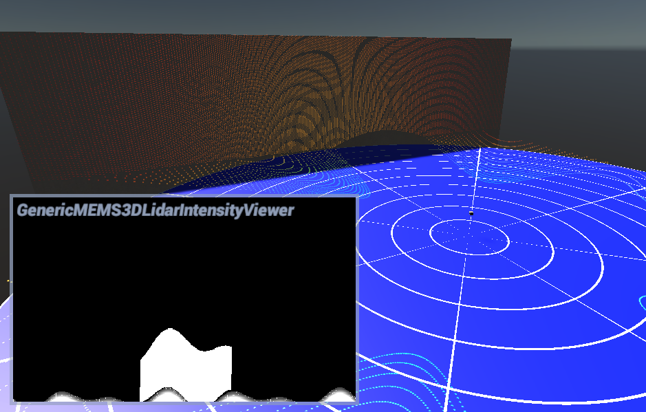
| Intensity | A corresponding render texture with the perceived intensity for each pixel. |
| OutTranscode | Provides a context for executing sampling custom passes, which then passes through the GPU processing pipeline. |