Simulation environments
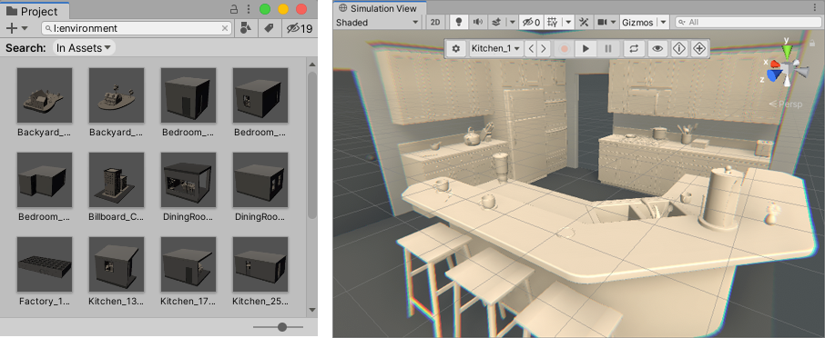
Simulation environments are prefabs that act as snapshots of the real world. In the Simulation view, you can preview how your content might react to surfaces and other world data your app detects. Unity MARS generates the list of environments it uses to simulate from prefabs in the Project which are tagged with the 'Environment' asset label. To see all of these environments, in the Project view, search for l:Environment.
Creating a simulated environment
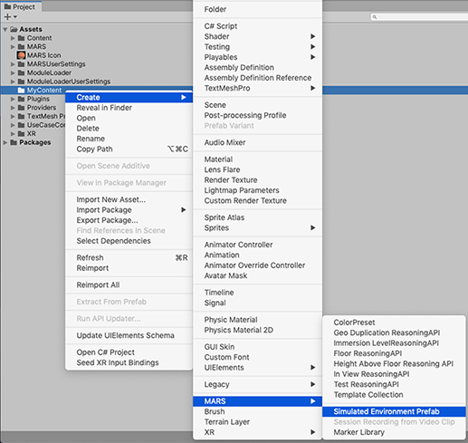
To create a new simulated environment, right-click in the Project view, then select Create > MARS > Simulated Environment Prefab.
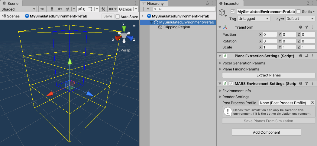
The root of this prefab will contain MARSEnvironmentSettings, PlaneExtractionSettings components, and an XRayRegion component inside the Clipping Region GameObject. The first two components allow you to set the default camera view for the simulation, set the starting position for device view, generate synthetic planes from your environment, and manipulate the interiors of environments.
Alternatively, you can set up an environment prefab from scratch. Follow these steps:
- Lay out the prefab as desired.
- Add a
MARSEnvironmentSettingscomponent on the root of the prefab. - Assign the 'Environment' asset label to the prefab. You can do this manually or click the Ensure registered in Simulation button to add the asset label and update simulation environments.
To see your environment in the Simulation view, from Unity's main menu, go to Window > MARS > Developer > Update Simulation Environments.
Animated environment elements
Any PlayableDirectors that a simulated environment contains will start automatically when used in any Unity MARS simulation view. To prevent these elements from constantly animating outside of temporal simulation (which prevents the Editor from idling), add a SimulatedPlayable to the Game Object with the Director. This the recommended way to add animated elements to your environments. As a best practice, use a parent to set an initial offset for animated elements.
Session recordings
When creating your environments, you can also record walkthroughs of your environments for later testing on your Unity MARS app. For more information, see documentation on session recordings
Environment settings
The MARSEnvironmentSettings component holds all the data related to viewing a simulated environment in a simulated view. In it, you can control the default camera pose, define where simulations start, and configure the following settings:
Environment info
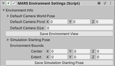
These properties control the starting camera position for Simulation view and the starting position for a MARSCamera.
Click the Save Environment View button to use the current Simulation view camera pose as the default Simulation view camera pose for the environment. This is usually a three-quarters view that lets you see the entire environment.
Click the Save Simulation Starting Pose button to use the current Simulation view camera pose as the starting pose of the Device view camera. Because the Device view simulates a user moving through the environment, this starting pose is generally where a user's head would be in the room when starting an AR session.
Render settings
Render settings override the Scene's Light Settings when the synthetic environment is being rendered with Composite Rendering in Unity MARS. These settings are limited to real-time lighting options since any baked settings are tied to a Scene.
Generating synthetic planes
Save planes from simulation
(This is the recommended way to create authoring planes for your environment)
When inspecting the active simulation environment in prefab mode, you can use the Save Planes From Simulation button to replace the environment's generated planes with the current planes in the simulation. This is useful if you want the environment to contain planes that you discovered dynamically in the Simulated Device view, rather than planes created from random raycasting throughout the whole environment (as described below).
To record planes in simulation, follow these steps:
- Start with a blank Scene.
- Add a plane visualizer.
- Open your environment in Simulation view.
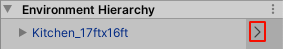
In the MARS panel, under the Environment Hierarchy drop-down, click on the arrow to the right of the environment. This sets your Scene view to look at the environment in isolation.
Start the Device View. From Unity's main menu, go to Window > MARS > Device View, then click the Play button in the Device View to start the simulation.
- Explore the Scene, and look at all the surfaces from natural angles. The plane visualizer displays the geometry of the planes as Unity MARS discovers them.
- Select the environment root in the hierarchy of prefab isolation (not in the Environment Hierarchy in the MARS panel).
- In the
MARS Environment Settingscomponent, click the Save Planes From Simulation button. - Optionally inspect, clean up, and adjust planes. Planes are SynthesizedObjects under the GeneratedPlanes root.
- Save your prefab.
Plane extraction settings
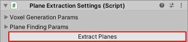
The PlaneExtractionSettings component lets you generate synthetic planes from Mesh Renderers in your environment.
Currently, only Mesh Renderers contribute to plane extraction. Unity MARS doesn't support generating planes from other types of renderers such as Skinned Mesh Renderers and Sprite Renderers.
Click the Extract Planes button to run this process.
Note: If there are previously generated planes in your Scene (parented to a Generated Planes GameObject), Unity MARS destroys them. If you want to preserve any of these planes you can move them out of the hierarchy of the parent before extracting planes.
Voxel generation parameters
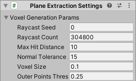
The first step of plane extraction involves generating a point cloud from environment meshes and adding each point to one of 6 grids of voxels (one for each cardinal direction in 3D). To create the point cloud, Unity MARS raycasts from random positions within the Scene bounds. There are parameters for how the rays are generated, how big the voxels are, and how points are added to voxels. Set Raycast Count to the square footage of your environment * 50,000 for good coverage during plane extraction. For more information on the parameters, hover your mouse cursor over each setting to see a short description for it.
Plane finding parameters
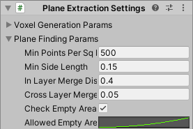
In the next step, planes are found in each voxel grid based on which voxels have a sufficient number of points. Parameters for this step include point density threshold, minimum plane size, plane merge distances, and allowed empty area taken up by planes. Setting In Layer Merge Distance between .2 and .4 will generally give you clean authoring planes. For more information on the parameters, hover your mouse cursor over each setting to see a short description for it.
XRay region component
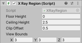
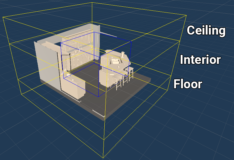
The XRay Region component is located inside the Clipping Region GameObject when creating a simulated environment prefab. XRay Regions set areas of an environment that can be seen through outer walls and other obstructions. An XRay is split into three regions: ceiling, interior, and floor. Unity MARS culls a region based on the following criteria:
- The ceiling is culled entirely if the camera is above it; otherwise, it is completely visible.
- The floor is culled entirely if the camera is below it; otherwise, it is completely visible.
- The interior is culled with a camera facing billboard centered at the position of the
XRayRegioncomponent.
In the example below, the billboard is pushed towards the camera based on the Clip Offset parameter of the XRay Region component. View Bounds specifies the general size of the culled area and should cover the entire room.
Any renderer that is influenced by the XRay system should use the MARS/Room X-Ray shader. Existing standard materials that use this shader are in the Content/Common/Materials and include floor, walls, ceiling, carpet, and accent.
XRay Collider component
XRay regions should also disable outer colliders so that a user can drag-and-drop content inside the environment. To enable this functionality, any outer collider should have the XRay Collider component attached to it.