UV Tool
The UV Tool allows you to view and modify UVs, directly in the Editor.
Unlike the default Unity Editor, which is limited to displaying UV information for one mesh at a time and does not offer editing capabilities, the UV Tool allows you to view and manipulate UVs across multiple selected GameObjects (and Meshes) simultaneously. This capability is crucial for complex projects involving multiple assets, like CAD/engineering models, which natively lack UV information.
How to
- Open the UV Tool from menu
Window>Rendering>UV Tool. - Select the GameObjects for which you want to view or modify the UVs.
- You can modify the selection of GameObjects while keeping the UV Tool window open; the UV layout is updated accordingly
- Use the Viewer Settings and actions from Modify UVs on the left-hand side of the window to visualize and modify UVs.
Viewer settings
| Parameter | Description |
|---|---|
| Shading Mode | Choose the display mode for UVs. Select Wireframe to see only the edges of UV islands, or Shaded to view filled areas for better visualization of surface coverage.Note: Wireframe mode not available with Unity 2022.3 with URP. |
| UV Channel | Select a UV channel to display in the viewer. Only channels with existing UV information are listed (up to 8). |
| Identify | Enable to automatically focus the Scene view on the corresponding triangles when hovering over UVs in the viewer. Enhances navigation and spatial understanding of UVs in relation to the 3D model. |
| Grid Color | Pick a color for the grid in the viewer. Customize the grid appearance to improve visibility and contrast with UVs. |
| Texture | Select a texture from the current Unity project to use as a background in the viewer. Displays in the 0-1 UV space to help visualize UV mapping. |
Tip
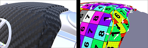
The UV Tool can be used in combination with the additional draw modes UV0 and UV1 to help you understand the UV layout in relation to the 3D model.
Modify UVs
| Action | Description |
|---|---|
| Create UVs | Create boxed projected UVs. As this function changes data at Mesh level, any modification to a Mesh will be visible for each GameObject using that Mesh, regardless of the input. |
| Create UVs for Lightmaps | Generate UVs for Unity lightmapping on channel 1. |
| Remove UVs | Remove existing UVs from meshes for the selected channel(s). Use this option to clear UV data and start with a clean slate. |
| Copy UVs | Duplicate UVs from one channel to another. Facilitates the reuse of UV layouts across different channels. |
| Repack UVs | Reorganize UV islands in standard 0-1 range to optimize texture space usage for the chosen UV channel(s). Minimizes wasted space and reduces texture seams. |
| Normalize UVs | Adjust UVs to fit within a standard 0-1 range. Ensures consistent scaling and positioning across the UV map. |
| Scale UVs To Real World Size | Rescale UVs to ensure the texture' scale matches the intended real-world size, improving realism and accuracy. |
More about UVs
To bring realism and quality to a 3D model in a Real-Time 3D experience, textures are often used in the materials applied to the 3D model. To define how these 2D textures are wrapped around the 3D model meshes, texture coordinates, also called UVs, are required. UV Mapping is the action of creating UVs for 3D meshes.
Here is an example of a CAD model transformed into a mesh with UVs to correctly display textured materials:
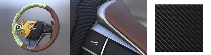
UVs are required for:
- Repeatable textures (also called seamless or tileable textures): they are images made of repeatable patterns, used to mimic how materials such as wood, carbon, fabric, brushed aluminum… behave in the real world. They generally use the first UV channel stored in a mesh (UV channel 0)
- Lightmaps, used to store lighting/shadows, Ambient Occlusion, Global Illumination… They generally use the second UV channel stored in a mesh (UV channel 1).
Both participate in bringing quality and realism to a 3D model in a virtual scene.
UV editing (or UV Mapping) is one of the most tedious and complex tasks when creating 3D models for virtual experiences, and users strive for automatic solutions, as much as possible. Manual UV unwrapping will always be necessary for advanced control over UV creation, and an area reserved for experts (and DCC tools).
Tip
Lots of great tips and information about UVs are available in this documentation page of Khronos Group's Real-time Asset Creation Guidelines
UVs and CAD models
CAD models come from CAD software where textures and UVs are generally not required, because realism is not a key aspect. But if you wish to leverage your CAD data to create realistic content for Real-Time 3D experiences, a correct texturing becomes necessary.
Generating UVs with Toolkit
To generate UVs with Asset Transformer Toolkit, several options exist:
- From the UV Tool, the Toolbox, and the Rule Engine: use the Create UVs and Create Lightmaps UVs actions.
- When importing a CAD/3D model, enable the
Create Ch.0 UVsandCreate Lightmaps UVsimport parameters.Note
If the
Create Ch.0 UVsandCreate Lightmaps UVssettings are disabled, the import process preserves UVs existing in the imported model. They can be viewed and modified using the UV Tool.
UV generation method
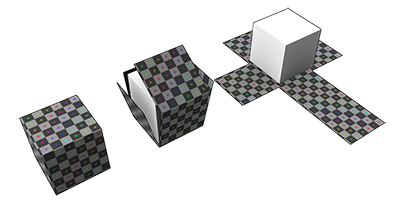
With the Create UVs action, UVs are generated with a box projection (along each direction of the object's Bounding Box). This method is fast, automatic and gives acceptable results in most cases. However it has limitation, as visible below:
With the Create Lightmaps UVs action, UVs are obtained by a box projection plus a UV repack, which gives acceptable results, but potentially unoptimized for baking (small and stretched islands).
Tip
Very high standards of quality can only be reached with manual UV unwrapping, with tools available in DCC software like Autodesk 3DSMax and Maya, Blender. Manually unwrapping tessellated CAD models can be challenging, as they are generally more dense (higher polycount) compared to 3D objects created with polygonal modeling.