Visualizing vertex data
These example shadersA program that runs on the GPU. More info
See in Glossary for the Built-in Render PipelineA series of operations that take the contents of a Scene, and displays them on a screen. Unity lets you choose from pre-built render pipelines, or write your own. Glossary for the Built-in Render PipelineA series of operations that take the contents of a Scene, and displays them on a screen. Unity lets you choose from pre-built render pipelines, or write your own. More info
See in Glossary demonstrate different ways of visualizing vertex data.
For information on writing shaders, see Writing shaders.
Visualizing UVs
The following example shader visualizes the first set of UVs of a meshThe main graphics primitive of Unity. Meshes make up a large part of your 3D worlds. Unity supports triangulated or Quadrangulated polygon meshes. Nurbs, Nurms, Subdiv surfaces must be converted to polygons. More info
See in Glossary. This shader is useful for debugging the coordinates.
The code defines a struct called appdata as its vertex shaderA program that runs on each vertex of a 3D model when the model is being rendered. More info
See in Glossary input. This struct takes the vertex position and the first texture coordinate as its inputs.
Shader "Debug/UV 1" {
SubShader {
    Pass {
        HLSLPROGRAM
        #pragma vertex vert
        #pragma fragment frag
            #include "UnityCG.cginc"

        // vertex input: position, UV
        struct appdata {
            float4 vertex : POSITION;
            float4 texcoord : TEXCOORD0;
        };

        struct v2f {
            float4 pos : SV_POSITION;
            float4 uv : TEXCOORD0;
        };

        v2f vert (appdata v) {
            v2f o;
            o.pos = UnityObjectToClipPos(v.vertex);
            o.uv = float4( v.texcoord.xy, 0, 0 );
            return o;
        }

        half4 frag( v2f i ) : SV_Target {
            half4 c = frac( i.uv );
            if (any(saturate(i.uv) - i.uv))
                c.b = 0.5;
            return c;
        }
        ENDHLSL
    }
}
}
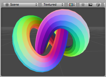
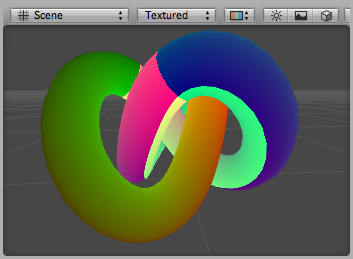
Here, UV coordinates are visualized as red and green colors, while an additional blue tint has been applied to coordinates outside of the 0 to 1 range:
This variation on the same shader visualizes the second UV set:
Shader "Debug/UV 2" {
SubShader {
    Pass {
        HLSLPROGRAM
        #pragma vertex vert
        #pragma fragment frag
            #include "UnityCG.cginc"

        // vertex input: position, second UV
        struct appdata {
            float4 vertex : POSITION;
            float4 texcoord1 : TEXCOORD1;
        };

        struct v2f {
            float4 pos : SV_POSITION;
            float4 uv : TEXCOORD0;
        };

        v2f vert (appdata v) {
            v2f o;
            o.pos = UnityObjectToClipPos(v.vertex );
            o.uv = float4( v.texcoord1.xy, 0, 0 );
            return o;
        }

        half4 frag( v2f i ) : SV_Target {
            half4 c = frac( i.uv );
            if (any(saturate(i.uv) - i.uv))
                c.b = 0.5;
            return c;
        }
        ENDHLSL
    }
}
}
Visualizing vertex colors
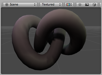
The following shader uses the vertex position and the per-vertex colors as the vertex shader inputs (defined in structure appdata).
Shader "Debug/Vertex color" {
SubShader {
    Pass {
        HLSLPROGRAM
        #pragma vertex vert
        #pragma fragment frag
        #include "UnityCG.cginc"

        // vertex input: position, color
        struct appdata {
            float4 vertex : POSITION;
            fixed4 color : COLOR;
        };

        struct v2f {
            float4 pos : SV_POSITION;
            fixed4 color : COLOR;
        };

        v2f vert (appdata v) {
            v2f o;
            o.pos = UnityObjectToClipPos(v.vertex );
            o.color = v.color;
            return o;
        }

        fixed4 frag (v2f i) : SV_Target { return i.color; }
        ENDHLSL
    }
}
}
Visualizing normals
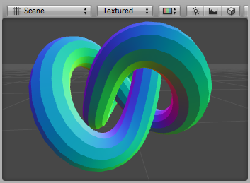
The following shader uses the vertex position and the normal as the vertex shader inputs (defined in the structure appdata). The normal’s X,Y & Z components are visualized as RGB colors. Because the normal components are in the –1 to 1 range, we scale and bias them so that the output colors are displayable in the 0 to 1 range.
Shader "Debug/Normals" {
SubShader {
    Pass {
        HLSLPROGRAM
        #pragma vertex vert
        #pragma fragment frag
        #include "UnityCG.cginc"

        // vertex input: position, normal
        struct appdata {
            float4 vertex : POSITION;
            float3 normal : NORMAL;
        };

        struct v2f {
            float4 pos : SV_POSITION;
            fixed4 color : COLOR;
        };

        v2f vert (appdata v) {
            v2f o;
            o.pos = UnityObjectToClipPos(v.vertex );
            o.color.xyz = v.normal * 0.5 + 0.5;
            o.color.w = 1.0;
            return o;
        }

        fixed4 frag (v2f i) : SV_Target { return i.color; }
        ENDHLSL
    }
}
}
Visualizing tangents and binormals
Tangent and binormal vectors are used for normal mapping. In Unity only the tangent vector is stored in vertices, and the binormal is derived from the normal and tangent values.
The following shader uses the vertex position and the tangent as vertex shader inputs (defined in structure appdata). Tangent’s x,y and z components are visualized as RGB colors. Because the normal components are in the –1 to 1 range, we scale and bias them so that the output colors are in a displayable 0 to 1 range.
Shader "Debug/Tangents" {
SubShader {
    Pass {
        HLSLPROGRAM
        #pragma vertex vert
        #pragma fragment frag
        #include "UnityCG.cginc"

        // vertex input: position, tangent
        struct appdata {
            float4 vertex : POSITION;
            float4 tangent : TANGENT;
        };

        struct v2f {
            float4 pos : SV_POSITION;
            fixed4 color : COLOR;
        };

        v2f vert (appdata v) {
            v2f o;
            o.pos = UnityObjectToClipPos(v.vertex );
            o.color = v.tangent * 0.5 + 0.5;
            return o;
        }

        fixed4 frag (v2f i) : SV_Target { return i.color; }
        ENDHLSL
    }
}
}
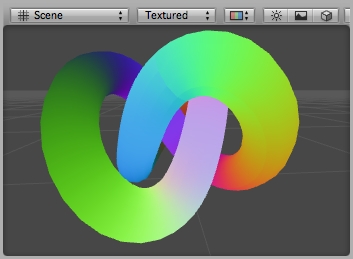
The following shader visualizes bitangents. It uses the vertex position, normal and tangent values as vertex inputs. The bitangent (sometimes called binormal) is calculated from the normal and tangent values. It needs to be scaled and biased into a displayable 0 to 1 range.
Shader "Debug/Bitangents" {
SubShader {
    Pass {
        Fog { Mode Off }
        HLSLPROGRAM
        #pragma vertex vert
        #pragma fragment frag
        #include "UnityCG.cginc"

        // vertex input: position, normal, tangent
        struct appdata {
            float4 vertex : POSITION;
            float3 normal : NORMAL;
            float4 tangent : TANGENT;
        };

        struct v2f {
            float4 pos : SV_POSITION;
            float4 color : COLOR;
        };

        v2f vert (appdata v) {
            v2f o;
            o.pos = UnityObjectToClipPos(v.vertex );
            // calculate bitangent
            float3 bitangent = cross( v.normal, v.tangent.xyz ) * v.tangent.w;
            o.color.xyz = bitangent * 0.5 + 0.5;
            o.color.w = 1.0;
            return o;
        }

        fixed4 frag (v2f i) : SV_Target { return i.color; }
        ENDHLSL
    }
}
}
