- Unity User Manual (5.5)
- Графика
- Справка по графическим возможностям
- Shader Reference
- Программирование вершинных и фрагментных (пиксельных) шейдеров
- Примеры вершинных и фрагментных шейдеров
Примеры вершинных и фрагментных шейдеров
This page contains vertex and fragment program examples. For a basic introduction to shaders, see the shader tutorials: Part 1 and Part 2. For an easy way of writing regular material shaders, see Surface Shaders.
You can download the examples shown below as a zipped Unity project.
- Создание меша
If you are not familiar with Unity’s Scene View, Hierarchy View, Project View and Inspector, now would be a good time to read the first few sections from the manual, starting with Unity Basics.
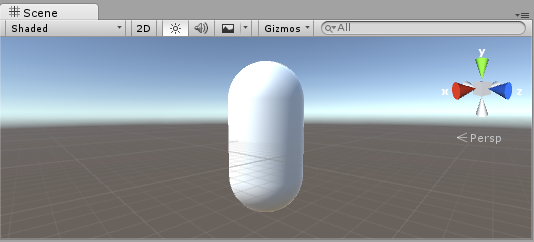
The first step is to create some objects which you will use to test your shaders. Select Game Object > 3D Object > Capsule in the main menu. Then position the camera so it shows the capsule. Double-click the Capsule in the Hierarchy to focus the scene view on it, then select the Main Camera object and click Game object > Align with View from the main menu.
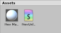
Создайте новый материал нажав Create в окне Project и выбрав Material. В окне Project появится новый материал с названием New Material. Измените имя материала на что-то более наглядное, например, Material-ShaderLab.

- Создание шейдера
Now create a new Shader asset in a similar way. Select Create > Shader > Unlit Shader from the menu in the Project View. This creates a basic shader that just displays a texture without any lighting.
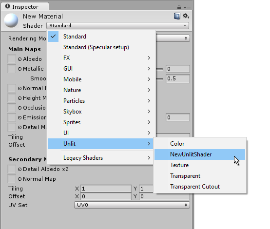
Other entries in the Create > Shader menu create barebone shaders or other types, for example a basic surface shader.
- Связь меша, материала и шейдера
Make the material use the shader via the material’s inspector, or just drag the shader asset over the material asset in the Project View. The material inspector will display a white sphere when it uses this shader.
Now drag the material onto your mesh object in either the Scene or the Hierarchy views. Alternatively, select the object, and in the inspector make it use the material in the Mesh Renderer component’s Materials slot.
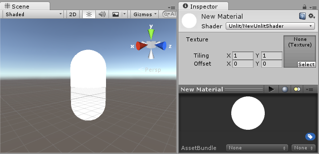
With these things set up, you can now begin looking at the shader code, and you will see the results of your changes to the shader on the capsule in the Scene View.
- Создание шейдера
To begin examining the code of the shader, double-click the shader asset in the Project View. The shader code will open in your script editor (MonoDevelop or Visual Studio).
The shader starts off with this code:
Shader "Unlit/NewUnlitShader"
{
    Properties
    {
        _MainTex ("Texture", 2D) = "white" {}
    }
    SubShader
    {
        Tags { "RenderType"="Opaque" }
        LOD 100

        Pass
        {
            CGPROGRAM
            #pragma vertex vert
            #pragma fragment frag
            // make fog work
            #pragma multi_compile_fog

            #include "UnityCG.cginc"

            struct appdata
            {
                float4 vertex : POSITION;
                float2 uv : TEXCOORD0;
            };

            struct v2f
            {
                float2 uv : TEXCOORD0;
                UNITY_FOG_COORDS(1)
                float4 vertex : SV_POSITION;
            };

            sampler2D _MainTex;
            float4 _MainTex_ST;

            v2f vert (appdata v)
            {
                v2f o;
                o.vertex = UnityObjectToClipPos(v.vertex);
                o.uv = TRANSFORM_TEX(v.uv, _MainTex);
                UNITY_TRANSFER_FOG(o,o.vertex);
                return o;
            }

            fixed4 frag (v2f i) : SV_Target
            {
                // sample the texture
                fixed4 col = tex2D(_MainTex, i.uv);
                // apply fog
                UNITY_APPLY_FOG(i.fogCoord, col);
                return col;
            }
            ENDCG
        }
    }
}
This initial shader does not look very simple! But don’t worry, we will go over each part step-by-step.
Let’s see the main parts of our simple shader.
Shader
The Shader command contains a string with the name of the shader. You can use forward slash characters “/” to place your shader in sub-menus when selecting your shader in the Material inspector.
Свойства
The Properties block contains shader variables (textures, colors etc.) that will be saved as part of the Material, and displayed in the material inspector. In our unlit shader template, there is a single texture property declared.
SubShader
A Shader can contain one or more SubShaders, which are primarily used to implement shaders for different GPU capabilities. In this tutorial we’re not much concerned with that, so all our shaders will contain just one SubShader.
Pass
Each SubShader is composed of a number of passes, and each Pass represents an execution of the vertex and fragment code for the same object rendered with the material of the shader. Many simple shaders use just one pass, but shaders that interact with lighting might need more (see Lighting Pipeline for details). Commands inside Pass typically setup fixed function state, for example blending modes.
CGPROGRAM .. ENDCG
These keywords surround portions of HLSL code within the vertex and fragment shaders. Typically this is where most of the interesting code is. See vertex and fragment shaders for details.
Простой шейдер
The unlit shader template does a few more things than would be absolutely needed to display an object with a texture. For example, it supports Fog, and texture tiling/offset fields in the material. Let’s simplify the shader to bare minimum, and add more comments:
Shader "Unlit/SimpleUnlitTexturedShader"
{
    Properties
    {
        // we have removed support for texture tiling/offset,
        // so make them not be displayed in material inspector
        [NoScaleOffset] _MainTex ("Texture", 2D) = "white" {}
    }
    SubShader
    {
        Pass
        {
            CGPROGRAM
            // use "vert" function as the vertex shader
            #pragma vertex vert
            // use "frag" function as the pixel (fragment) shader
            #pragma fragment frag

            // vertex shader inputs
            struct appdata
            {
                float4 vertex : POSITION; // vertex position
                float2 uv : TEXCOORD0; // texture coordinate
            };

            // vertex shader outputs ("vertex to fragment")
            struct v2f
            {
                float2 uv : TEXCOORD0; // texture coordinate
                float4 vertex : SV_POSITION; // clip space position
            };

            // vertex shader
            v2f vert (appdata v)
            {
                v2f o;
                // transform position to clip space
                // (multiply with model*view*projection matrix)
                o.vertex = mul(UNITY_MATRIX_MVP, v.vertex);
                // just pass the texture coordinate
                o.uv = v.uv;
                return o;
            }

            // texture we will sample
            sampler2D _MainTex;

            // pixel shader; returns low precision ("fixed4" type)
            // color ("SV_Target" semantic)
            fixed4 frag (v2f i) : SV_Target
            {
                // sample texture and return it
                fixed4 col = tex2D(_MainTex, i.uv);
                return col;
            }
            ENDCG
        }
    }
}
The Vertex Shader is a program that runs on each vertex of the 3D model. Quite often it does not do anything particularly interesting. Here we just transform vertex position from object space into so called “clip space”, which is what’s used by the GPU to rasterize the object on screen. We also pass the input texture coordinate unmodified - we’ll need it to sample the texture in the fragment shader.
The Fragment Shader is a program that runs on each and every pixel that object occupies on-screen, and is usually used to calculate and output the color of each pixel. Usually there are millions of pixels on the screen, and the fragment shaders are executed for all of them! Optimizing fragment shaders is quite an important part of overall game performance work.
Some variable or function definitions are followed by a Semantic Signifier - for example : POSITION or : SV_Target. These semantics signifiers communicate the “meaning” of these variables to the GPU. See the shader semantics page for details.
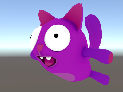
When used on a nice model with a nice texture, our simple shader looks pretty good!
Простой шейдер
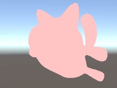
Let’s simplify the shader even more – we’ll make a shader that draws the whole object in a single color. This is not terribly useful, but hey we’re learning here.
Shader "Unlit/SingleColor"
{
    Properties
    {
        // Color property for material inspector, default to white
        _Color ("Main Color", Color) = (1,1,1,1)
    }
    SubShader
    {
        Pass
        {
            CGPROGRAM
            #pragma vertex vert
            #pragma fragment frag

            // vertex shader
            // this time instead of using "appdata" struct, just spell inputs manually,
            // and instead of returning v2f struct, also just return a single output
            // float4 clip position
            float4 vert (float4 vertex : POSITION) : SV_POSITION
            {
                return mul(UNITY_MATRIX_MVP, vertex);
            }

            // color from the material
            fixed4 _Color;

            // pixel shader, no inputs needed
            fixed4 frag () : SV_Target
            {
                return _Color; // just return it
            }
            ENDCG
        }
    }
}
This time instead of using structs for input (appdata) and output (v2f), the shader functions just spell out inputs manually. Both ways work, and which you choose to use depends on your coding style and preference.
Using mesh normals for fun and profit
Let’s proceed with a shader that displays mesh normals in world space. Without further ado:
Shader "Unlit/WorldSpaceNormals"
{
    // no Properties block this time!
    SubShader
    {
        Pass
        {
            CGPROGRAM
            #pragma vertex vert
            #pragma fragment frag
            // include file that contains UnityObjectToWorldNormal helper function
            #include "UnityCG.cginc"

            struct v2f {
                // we'll output world space normal as one of regular ("texcoord") interpolators
                half3 worldNormal : TEXCOORD0;
                float4 pos : SV_POSITION;
            };

            // vertex shader: takes object space normal as input too
            v2f vert (float4 vertex : POSITION, float3 normal : NORMAL)
            {
                v2f o;
                o.pos = UnityObjectToClipPos(vertex);
                // UnityCG.cginc file contains function to transform
                // normal from object to world space, use that
                o.worldNormal = UnityObjectToWorldNormal(normal);
                return o;
            }

            fixed4 frag (v2f i) : SV_Target
            {
                fixed4 c = 0;
                // normal is a 3D vector with xyz components; in -1..1
                // range. To display it as color, bring the range into 0..1
                // and put into red, green, blue components
                c.rgb = i.worldNormal*0.5+0.5;
                return c;
            }
            ENDCG
        }
    }
}
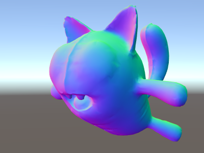
Besides resulting in pretty colors, normals are used for all sorts of graphics effects – lighting, reflections, silhouettes and so on.
In the shader above, we started using one of Unity’s built-in shader include files. Here, UnityCG.cginc was used which contains a handy function UnityObjectToWorldNormal. We have also used the utility function UnityObjectToClipPos, which transforms the vertex from object space to the screen. This just makes the code easier to read and is more efficient under certain circumstances.
We’ve seen that data can be passed from the vertex into fragment shader in so-called “interpolators” (or sometimes called “varyings”). In HLSL shading language they are typically labeled with TEXCOORDn semantic, and each of them can be up to a 4-component vector (see semantics page for details).
Also we’ve learned a simple technique in how to visualize normalized vectors (in –1.0 to +1.0 range) as colors: just multiply them by half and add half. See more vertex data visualization examples in vertex program inputs page.
Environment reflection using world-space normals
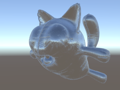
When a Skybox is used in the scene as a reflection source (see Lighting Window), then essentially a “default” Reflection Probe is created, containing the skybox data. A reflection probe is internally a Cubemap texture; we will extend the world-space normals shader above to look into it.
The code is starting to get a bit involved by now. Of course, if you want shaders that automatically work with lights, shadows, reflections and the rest of the lighting system, it’s way easier to use surface shaders. This example is intended to show you how to use parts of the lighting system in a “manual” way.
Shader "Unlit/SkyReflection"
{
    SubShader
    {
        Pass
        {
            CGPROGRAM
            #pragma vertex vert
            #pragma fragment frag
            #include "UnityCG.cginc"

            struct v2f {
                half3 worldRefl : TEXCOORD0;
                float4 pos : SV_POSITION;
            };

            v2f vert (float4 vertex : POSITION, float3 normal : NORMAL)
            {
                v2f o;
                o.pos = UnityObjectToClipPos(vertex);
                // compute world space position of the vertex
                float3 worldPos = mul(_Object2World, vertex).xyz;
                // compute world space view direction
                float3 worldViewDir = normalize(UnityWorldSpaceViewDir(worldPos));
                // world space normal
                float3 worldNormal = UnityObjectToWorldNormal(normal);
                // world space reflection vector
                o.worldRefl = reflect(-worldViewDir, worldNormal);
                return o;
            }

            fixed4 frag (v2f i) : SV_Target
            {
                // sample the default reflection cubemap, using the reflection vector
                half4 skyData = UNITY_SAMPLE_TEXCUBE(unity_SpecCube0, i.worldRefl);
                // decode cubemap data into actual color
                half3 skyColor = DecodeHDR (skyData, unity_SpecCube0_HDR);
                // output it!
                fixed4 c = 0;
                c.rgb = skyColor;
                return c;
            }
            ENDCG
        }
    }
}
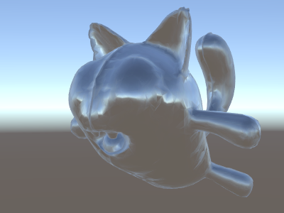
The example above uses several things from the built-in shader include files:
- unity_SpecCube0, unity_SpecCube0_HDR, Object2World, UNITY_MATRIX_MVP from the built-in shader variables. unity_SpecCube0 contains data for the active reflection probe.
- UNITY_SAMPLE_TEXCUBE is a built-in macro to sample a cubemap. Most regular cubemaps are declared and used using standard HLSL syntax (samplerCUBE and texCUBE), however the reflection probe cubemaps in Unity are declared in a special way to save on sampler slots. If you don’t know what that is, don’t worry, just know that in order to use unity_SpecCube0 cubemap you have to use UNITY_SAMPLE_TEXCUBE macro.
- UnityWorldSpaceViewDir function from UnityCG.cginc, and DecodeHDR function from the same file. The latter is used to get actual color from the reflection probe data – since Unity stores reflection probe cubemap in specially encoded way.
- reflect is just a built-in HLSL function to compute vector reflection around a given normal.
Environment reflection with a normal map
Often Normal Maps are used to create additional detail on objects, without creating additional geometry. Let’s see how to make a shader that reflects the environment, with a normal map texture.
Now the math is starting to get really involved, so we’ll do it in a few steps. In the shader above, the reflection direction was computed per-vertex (in the vertex shader), and the fragment shader was only doing the reflection probe cubemap lookup. However once we start using normal maps, the surface normal itself needs to be calculated on a per-pixel basis, which means we also have to compute how the environment is reflected per-pixel!
So first of all, let’s rewrite the shader above to do the same thing, except we will move some of the calculations to the fragment shader, so they are computed per-pixel:
Shader "Unlit/SkyReflection Per Pixel"
{
    SubShader
    {
        Pass
        {
            CGPROGRAM
            #pragma vertex vert
            #pragma fragment frag
            #include "UnityCG.cginc"

            struct v2f {
                float3 worldPos : TEXCOORD0;
                half3 worldNormal : TEXCOORD1;
                float4 pos : SV_POSITION;
            };

            v2f vert (float4 vertex : POSITION, float3 normal : NORMAL)
            {
                v2f o;
                o.pos = UnityObjectToClipPos(vertex);
                o.worldPos = mul(_Object2World, vertex).xyz;
                o.worldNormal = UnityObjectToWorldNormal(normal);
                return o;
            }

            fixed4 frag (v2f i) : SV_Target
            {
                // compute view direction and reflection vector
                // per-pixel here
                half3 worldViewDir = normalize(UnityWorldSpaceViewDir(i.worldPos));
                half3 worldRefl = reflect(-worldViewDir, i.worldNormal);

                // same as in previous shader
                half4 skyData = UNITY_SAMPLE_TEXCUBE(unity_SpecCube0, worldRefl);
                half3 skyColor = DecodeHDR (skyData, unity_SpecCube0_HDR);
                fixed4 c = 0;
                c.rgb = skyColor;
                return c;
            }
            ENDCG
        }
    }
}
That by itself does not give us much – the shader looks exactly the same, except now it runs slower since it does more calculations for each and every pixel on screen, instead of only for each of the model’s vertices. However, we’ll need these calculations really soon. Higher graphics fidelity often requires more complex shaders.
We’ll have to learn a new thing now too; the so-called “tangent space”. Normal map textures are most often expressed in a coordinate space that can be thought of as “following the surface” of the model. In our shader, we will need to to know the tangent space basis vectors, read the normal vector from the texture, transform it into world space, and then do all the math from the above shader. Let’s get to it!
Shader "Unlit/SkyReflection Per Pixel"
{
    Properties {
        // normal map texture on the material,
        // default to dummy "flat surface" normalmap
        _BumpMap("Normal Map", 2D) = "bump" {}
    }
    SubShader
    {
        Pass
        {
            CGPROGRAM
            #pragma vertex vert
            #pragma fragment frag
            #include "UnityCG.cginc"

            struct v2f {
                float3 worldPos : TEXCOORD0;
                // these three vectors will hold a 3x3 rotation matrix
                // that transforms from tangent to world space
                half3 tspace0 : TEXCOORD1; // tangent.x, bitangent.x, normal.x
                half3 tspace1 : TEXCOORD2; // tangent.y, bitangent.y, normal.y
                half3 tspace2 : TEXCOORD3; // tangent.z, bitangent.z, normal.z
                // texture coordinate for the normal map
                float2 uv : TEXCOORD4;
                float4 pos : SV_POSITION;
            };

            // vertex shader now also needs a per-vertex tangent vector.
            // in Unity tangents are 4D vectors, with the .w component used to
            // indicate direction of the bitangent vector.
            // we also need the texture coordinate.
            v2f vert (float4 vertex : POSITION, float3 normal : NORMAL, float4 tangent : TANGENT, float2 uv : TEXCOORD0)
            {
                v2f o;
                o.pos = UnityObjectToClipPos(vertex);
                o.worldPos = mul(_Object2World, vertex).xyz;
                half3 wNormal = UnityObjectToWorldNormal(normal);
                half3 wTangent = UnityObjectToWorldDir(tangent.xyz);
                // compute bitangent from cross product of normal and tangent
                half tangentSign = tangent.w * unity_WorldTransformParams.w;
                half3 wBitangent = cross(wNormal, wTangent) * tangentSign;
                // output the tangent space matrix
                o.tspace0 = half3(wTangent.x, wBitangent.x, wNormal.x);
                o.tspace1 = half3(wTangent.y, wBitangent.y, wNormal.y);
                o.tspace2 = half3(wTangent.z, wBitangent.z, wNormal.z);
                o.uv = uv;
                return o;
            }

            // normal map texture from shader properties
            sampler2D _BumpMap;

            fixed4 frag (v2f i) : SV_Target
            {
                // sample the normal map, and decode from the Unity encoding
                half3 tnormal = UnpackNormal(tex2D(_BumpMap, i.uv));
                // transform normal from tangent to world space
                half3 worldNormal;
                worldNormal.x = dot(i.tspace0, tnormal);
                worldNormal.y = dot(i.tspace1, tnormal);
                worldNormal.z = dot(i.tspace2, tnormal);

                // rest the same as in previous shader
                half3 worldViewDir = normalize(UnityWorldSpaceViewDir(i.worldPos));
                half3 worldRefl = reflect(-worldViewDir, worldNormal);
                half4 skyData = UNITY_SAMPLE_TEXCUBE(unity_SpecCube0, worldRefl);
                half3 skyColor = DecodeHDR (skyData, unity_SpecCube0_HDR);
                fixed4 c = 0;
                c.rgb = skyColor;
                return c;
            }
            ENDCG
        }
    }
}
Phew, that was quite involved. But look, normal mapped reflections!
Adding more textures
Let’s add more textures to the normal-mapped, sky-reflecting shader above. We’ll add the base color texture, seen in the first unlit example, and an occlusion map to darken the cavities.
Shader "Unlit/More Textures"
{
    Properties {
        // three textures we'll use in the material
        _MainTex("Base texture", 2D) = "white" {}
        _OcclusionMap("Occlusion", 2D) = "white" {}
        _BumpMap("Normal Map", 2D) = "bump" {}
    }
    SubShader
    {
        Pass
        {
            CGPROGRAM
            #pragma vertex vert
            #pragma fragment frag
            #include "UnityCG.cginc"

            // exactly the same as in previous shader
            struct v2f {
                float3 worldPos : TEXCOORD0;
                half3 tspace0 : TEXCOORD1;
                half3 tspace1 : TEXCOORD2;
                half3 tspace2 : TEXCOORD3;
                float2 uv : TEXCOORD4;
                float4 pos : SV_POSITION;
            };
            v2f vert (float4 vertex : POSITION, float3 normal : NORMAL, float4 tangent : TANGENT, float2 uv : TEXCOORD0)
            {
                v2f o;
                o.pos = UnityObjectToClipPos(vertex);
                o.worldPos = mul(_Object2World, vertex).xyz;
                half3 wNormal = UnityObjectToWorldNormal(normal);
                half3 wTangent = UnityObjectToWorldDir(tangent.xyz);
                half tangentSign = tangent.w * unity_WorldTransformParams.w;
                half3 wBitangent = cross(wNormal, wTangent) * tangentSign;
                o.tspace0 = half3(wTangent.x, wBitangent.x, wNormal.x);
                o.tspace1 = half3(wTangent.y, wBitangent.y, wNormal.y);
                o.tspace2 = half3(wTangent.z, wBitangent.z, wNormal.z);
                o.uv = uv;
                return o;
            }

            // textures from shader properties
            sampler2D _MainTex;
            sampler2D _OcclusionMap;
            sampler2D _BumpMap;

            fixed4 frag (v2f i) : SV_Target
            {
                // same as from previous shader...
                half3 tnormal = UnpackNormal(tex2D(_BumpMap, i.uv));
                half3 worldNormal;
                worldNormal.x = dot(i.tspace0, tnormal);
                worldNormal.y = dot(i.tspace1, tnormal);
                worldNormal.z = dot(i.tspace2, tnormal);
                half3 worldViewDir = normalize(UnityWorldSpaceViewDir(i.worldPos));
                half3 worldRefl = reflect(-worldViewDir, worldNormal);
                half4 skyData = UNITY_SAMPLE_TEXCUBE(unity_SpecCube0, worldRefl);
                half3 skyColor = DecodeHDR (skyData, unity_SpecCube0_HDR);
                fixed4 c = 0;
                c.rgb = skyColor;

                // modulate sky color with the base texture, and the occlusion map
                fixed3 baseColor = tex2D(_MainTex, i.uv).rgb;
                fixed occlusion = tex2D(_OcclusionMap, i.uv).r;
                c.rgb *= baseColor;
                c.rgb *= occlusion;

                return c;
            }
            ENDCG
        }
    }
}
Balloon cat is looking good!

Примеры вершинных и фрагментных шейдеров
Procedural checkerboard pattern
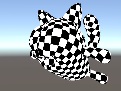
Here’s a shader that outputs a checkerboard pattern based on texture coordinates of a mesh:
Shader "Unlit/Checkerboard"
{
    Properties
    {
        _Density ("Density", Range(2,50)) = 30
    }
    SubShader
    {
        Pass
        {
            CGPROGRAM
            #pragma vertex vert
            #pragma fragment frag
            #include "UnityCG.cginc"

            struct v2f
            {
                float2 uv : TEXCOORD0;
                float4 vertex : SV_POSITION;
            };

            float _Density;

            v2f vert (float4 pos : POSITION, float2 uv : TEXCOORD0)
            {
                v2f o;
                o.vertex = UnityObjectToClipPos(pos);
                o.uv = uv * _Density;
                return o;
            }

            fixed4 frag (v2f i) : SV_Target
            {
                float2 c = i.uv;
                c = floor(c) / 2;
                float checker = frac(c.x + c.y) * 2;
                return checker;
            }
            ENDCG
        }
    }
}
The density slider in the Properties block controls how dense the checkerboard is. In the vertex shader, the mesh UVs are multiplied by the density value to take them from a range of 0 to 1 to a range of 0 to density. Let’s say the density was set to 30 - this will make i.uv input into the fragment shader contain floating point values from zero to 30 for various places of the mesh being rendered.
Then the fragment shader code takes only the integer part of the input coordinate using HLSL’s built-in floor function, and divides it by two. Recall that the input coordinates were numbers from 0 to 30; this makes them all be “quantized” to values of 0, 0.5, 1, 1.5, 2, 2.5, and so on. This was done on both the x and y components of the input coordinate.
Next up, we add these x and y coordinates together (each of them only having possible values of 0, 0.5, 1, 1.5, …) and only take the fractional part using another built-in HLSL function, frac. Result of this can only be either 0.0 or 0.5. We then multiply it by two to make it either 0.0 or 1.0, and output as a color (this results in black or white color respectively).
Tri-planar texturing
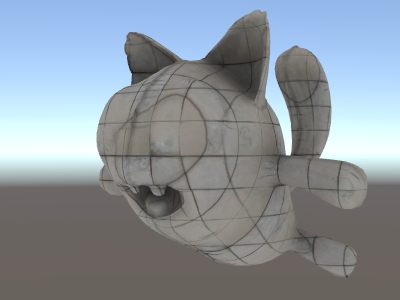
For complex or procedural meshes, instead of texturing them using the regular UV coordinates, it is sometimes useful to just “project” texture onto the object from three primary directions. This is called “tri-planar” texturing. The idea is to use surface normal to weight the three texture directions. Here’s the shader:
Shader "Unlit/Triplanar"
{
    Properties
    {
        _MainTex ("Texture", 2D) = "white" {}
        _Tiling ("Tiling", Float) = 1.0
        _OcclusionMap("Occlusion", 2D) = "white" {}
    }
    SubShader
    {
        Pass
        {
            CGPROGRAM
            #pragma vertex vert
            #pragma fragment frag
            #include "UnityCG.cginc"

            struct v2f
            {
                half3 objNormal : TEXCOORD0;
                float3 coords : TEXCOORD1;
                float2 uv : TEXCOORD2;
                float4 pos : SV_POSITION;
            };

            float _Tiling;

            v2f vert (float4 pos : POSITION, float3 normal : NORMAL, float2 uv : TEXCOORD0)
            {
                v2f o;
                o.pos = UnityObjectToClipPos(pos);
                o.coords = pos.xyz * _Tiling;
                o.objNormal = normal;
                o.uv = uv;
                return o;
            }

            sampler2D _MainTex;
            sampler2D _OcclusionMap;

            fixed4 frag (v2f i) : SV_Target
            {
                // use absolute value of normal as texture weights
                half3 blend = abs(i.objNormal);
                // make sure the weights sum up to 1 (divide by sum of x+y+z)
                blend /= dot(blend,1.0);
                // read the three texture projections, for x,y,z axes
                fixed4 cx = tex2D(_MainTex, i.coords.yz);
                fixed4 cy = tex2D(_MainTex, i.coords.xz);
                fixed4 cz = tex2D(_MainTex, i.coords.xy);
                // blend the textures based on weights
                fixed4 c = cx * blend.x + cy * blend.y + cz * blend.z;
                // modulate by regular occlusion map
                c *= tex2D(_OcclusionMap, i.uv);
                return c;
            }
            ENDCG
        }
    }
}
Calculating lighting
Typically when you want a shader that works with Unity’s lighting pipeline, you would write a surface shader. This does most of the “heavy lifting” for you, and your shader code just needs to define surface properties.
However in some cases you want to bypass the standard surface shader path; either because you want to only support some limited subset of whole lighting pipeline for performance reasons, or you want to do custom things that aren’t quite “standard lighting”. The following examples will show how to get to the lighting data from manually-written vertex and fragment shaders. Looking at the code generated by surface shaders (via shader inspector) is also a good learning resource.
Simple diffuse lighting
The first thing we need to do is to indicate that our shader does in fact need lighting information passed to it. Unity’s rendering pipeline supports various ways of rendering; here we’ll be using the default forward rendering one.
We’ll start by only supporting one directional light. Forward rendering in Unity works by rendering the main directional light, ambient, lightmaps and reflections in a single pass called ForwardBase. In the shader, this is indicated by adding a pass tag: Tags {“LightMode”=“ForwardBase”}. This will make directional light data be passed into shader via some built-in variables.
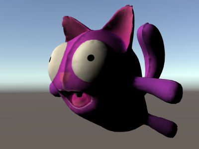
Here’s the shader that computes simple diffuse lighting per vertex, and uses a single main texture:
Shader "Lit/Simple Diffuse"
{
    Properties
    {
        [NoScaleOffset] _MainTex ("Texture", 2D) = "white" {}
    }
    SubShader
    {
        Pass
        {
            // indicate that our pass is the "base" pass in forward
            // rendering pipeline. It gets ambient and main directional
            // light data set up; light direction in _WorldSpaceLightPos0
            // and color in _LightColor0
            Tags {"LightMode"="ForwardBase"}

            CGPROGRAM
            #pragma vertex vert
            #pragma fragment frag
            #include "UnityCG.cginc" // for UnityObjectToWorldNormal
            #include "UnityLightingCommon.cginc" // for _LightColor0

            struct v2f
            {
                float2 uv : TEXCOORD0;
                fixed4 diff : COLOR0; // diffuse lighting color
                float4 vertex : SV_POSITION;
            };

            v2f vert (appdata_base v)
            {
                v2f o;
                o.vertex = UnityObjectToClipPos(v.vertex);
                o.uv = v.texcoord;
                // get vertex normal in world space
                half3 worldNormal = UnityObjectToWorldNormal(v.normal);
                // dot product between normal and light direction for
                // standard diffuse (Lambert) lighting
                half nl = max(0, dot(worldNormal, _WorldSpaceLightPos0.xyz));
                // factor in the light color
                o.diff = nl * _LightColor0;
                return o;
            }

            sampler2D _MainTex;

            fixed4 frag (v2f i) : SV_Target
            {
                // sample texture
                fixed4 col = tex2D(_MainTex, i.uv);
                // multiply by lighting
                col *= i.diff;
                return col;
            }
            ENDCG
        }
    }
}
This makes the object react to light direction - parts of it facing the light are illuminated, and parts facing away are not illuminated at all.
Diffuse lighting with ambient
The example above does not take any ambient lighting or light probes into account. Let’s fix this! It turns out we can do this by adding just a single line of code. Both ambient and light probe data is passed to shaders in Spherical Harmonics form, and ShadeSH9 function from UnityCG.cginc include file does all the work of evaluating it, given a world space normal.
Shader "Lit/Diffuse With Ambient"
{
    Properties
    {
        [NoScaleOffset] _MainTex ("Texture", 2D) = "white" {}
    }
    SubShader
    {
        Pass
        {
            Tags {"LightMode"="ForwardBase"}

            CGPROGRAM
            #pragma vertex vert
            #pragma fragment frag
            #include "UnityCG.cginc"
            #include "UnityLightingCommon.cginc"

            struct v2f
            {
                float2 uv : TEXCOORD0;
                fixed4 diff : COLOR0;
                float4 vertex : SV_POSITION;
            };

            v2f vert (appdata_base v)
            {
                v2f o;
                o.vertex = UnityObjectToClipPos(v.vertex);
                o.uv = v.texcoord;
                half3 worldNormal = UnityObjectToWorldNormal(v.normal);
                half nl = max(0, dot(worldNormal, _WorldSpaceLightPos0.xyz));
                o.diff = nl * _LightColor0;

                // the only difference from previous shader:
                // in addition to the diffuse lighting from the main light,
                // add illumination from ambient or light probes
                // ShadeSH9 function from UnityCG.cginc evaluates it,
                // using world space normal
                o.diff.rgb += ShadeSH9(half4(worldNormal,1));
                return o;
            }

            sampler2D _MainTex;

            fixed4 frag (v2f i) : SV_Target
            {
                fixed4 col = tex2D(_MainTex, i.uv);
                col *= i.diff;
                return col;
            }
            ENDCG
        }
    }
}
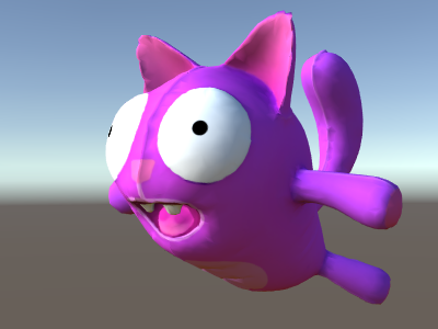
This shader is in fact starting to look very similar to the built-in Legacy Diffuse shader!
- Создание шейдера
Our shader currently can neither receive nor cast shadows. Let’s implement shadow casting first.
In order to cast shadows, a shader has to have a ShadowCaster pass type in any of its subshaders or any fallback. The ShadowCaster pass is used to render the object into the shadowmap, and typically it is fairly simple - the vertex shader only needs to evaluate the vertex position, and the fragment shader pretty much does not do anything. The shadowmap is only the depth buffer, so even the color output by the fragment shader does not really matter.
This means that for a lot of shaders, the shadow caster pass is going to be almost exactly the same (unless object has custom vertex shader based deformations, or has alpha cutout / semitransparent parts). The easiest way to pull it in is via UsePass shader command:
Pass
{
    // regular lighting pass
}
// pull in shadow caster from VertexLit built-in shader
UsePass "Legacy Shaders/VertexLit/SHADOWCASTER"
However we’re learning here, so let’s do the same thing “by hand” so to speak. For shorter code, we’ve replaced the lighting pass (“ForwardBase”) with code that only does untextured ambient. Below it, there’s a “ShadowCaster” pass that makes the object support shadow casting.
Shader "Lit/Shadow Casting"
{
    SubShader
    {
        // very simple lighting pass, that only does non-textured ambient
        Pass
        {
            Tags {"LightMode"="ForwardBase"}
            CGPROGRAM
            #pragma vertex vert
            #pragma fragment frag
            #include "UnityCG.cginc"
            struct v2f
            {
                fixed4 diff : COLOR0;
                float4 vertex : SV_POSITION;
            };
            v2f vert (appdata_base v)
            {
                v2f o;
                o.vertex = UnityObjectToClipPos(v.vertex);
                half3 worldNormal = UnityObjectToWorldNormal(v.normal);
                // only evaluate ambient
                o.diff.rgb = ShadeSH9(half4(worldNormal,1));
                o.diff.a = 1;
                return o;
            }
            fixed4 frag (v2f i) : SV_Target
            {
                return i.diff;
            }
            ENDCG
        }

        // shadow caster rendering pass, implemented manually
        // using macros from UnityCG.cginc
        Pass
        {
            Tags {"LightMode"="ShadowCaster"}

            CGPROGRAM
            #pragma vertex vert
            #pragma fragment frag
            #pragma multi_compile_shadowcaster
            #include "UnityCG.cginc"

            struct v2f {
                V2F_SHADOW_CASTER;
            };

            v2f vert(appdata_base v)
            {
                v2f o;
                TRANSFER_SHADOW_CASTER_NORMALOFFSET(o)
                return o;
            }

            float4 frag(v2f i) : SV_Target
            {
                SHADOW_CASTER_FRAGMENT(i)
            }
            ENDCG
        }
    }
}
Now there’s a plane underneath, using a regular built-in Diffuse shader, so that we can see our shadows working (remember, our current shader does not support receiving shadows yet!).
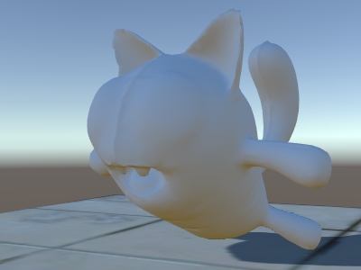
We’ve used the #pragma multi_compile_shadowcaster directive. This causes the shader to be compiled into several variants with different preprocessor macros defined for each (see multiple shader variants page for details). When rendering into the shadowmap, the cases of point lights vs other light types need slightly different shader code, that’s why this directive is needed.
- Создание шейдера
Implementing support for receiving shadows will require compiling the base lighting pass into several variants, to handle cases of “directional light without shadows” and “directional light with shadows” properly. #pragma multi_compile_fwdbase directive does this (see multiple shader variants for details). In fact it does a lot more: it also compiles variants for the different lightmap types, realtime GI being on or off etc. Currently we don’t need all that, so we’ll explicitly skip these variants.
Then to get actual shadowing computations, we’ll #include “AutoLight.cginc” shader include file and use SHADOW_COORDS, TRANSFER_SHADOW, SHADOW_ATTENUATION macros from it.
Here’s the shader:
Shader "Lit/Diffuse With Shadows"
{
    Properties
    {
        [NoScaleOffset] _MainTex ("Texture", 2D) = "white" {}
    }
    SubShader
    {
        Pass
        {
            Tags {"LightMode"="ForwardBase"}
            CGPROGRAM
            #pragma vertex vert
            #pragma fragment frag
            #include "UnityCG.cginc"
            #include "Lighting.cginc"

            // compile shader into multiple variants, with and without shadows
            // (we don't care about any lightmaps yet, so skip these variants)
            #pragma multi_compile_fwdbase nolightmap nodirlightmap nodynlightmap novertexlight
            // shadow helper functions and macros
            #include "AutoLight.cginc"

            struct v2f
            {
                float2 uv : TEXCOORD0;
                SHADOW_COORDS(1) // put shadows data into TEXCOORD1
                fixed3 diff : COLOR0;
                fixed3 ambient : COLOR1;
                float4 pos : SV_POSITION;
            };
            v2f vert (appdata_base v)
            {
                v2f o;
                o.pos = UnityObjectToClipPos(v.vertex);
                o.uv = v.texcoord;
                half3 worldNormal = UnityObjectToWorldNormal(v.normal);
                half nl = max(0, dot(worldNormal, _WorldSpaceLightPos0.xyz));
                o.diff = nl * _LightColor0.rgb;
                o.ambient = ShadeSH9(half4(worldNormal,1));
                // compute shadows data
                TRANSFER_SHADOW(o)
                return o;
            }

            sampler2D _MainTex;

            fixed4 frag (v2f i) : SV_Target
            {
                fixed4 col = tex2D(_MainTex, i.uv);
                // compute shadow attenuation (1.0 = fully lit, 0.0 = fully shadowed)
                fixed shadow = SHADOW_ATTENUATION(i);
                // darken light's illumination with shadow, keep ambient intact
                fixed3 lighting = i.diff * shadow + i.ambient;
                col.rgb *= lighting;
                return col;
            }
            ENDCG
        }

        // shadow casting support
        UsePass "Legacy Shaders/VertexLit/SHADOWCASTER"
    }
}
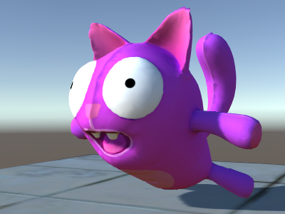
Look, we have shadows now!
Примеры вершинных и фрагментных шейдеров
Туман
Shader "Custom/TextureCoordinates/Fog" {
    SubShader {
        Pass {
            CGPROGRAM
            #pragma vertex vert
            #pragma fragment frag

            //Needed for fog variation to be compiled.
            #pragma multi_compile_fog

            #include "UnityCG.cginc"

            struct vertexInput {
                float4 vertex : POSITION;
                float4 texcoord0 : TEXCOORD0;
            };

            struct fragmentInput{
                float4 position : SV_POSITION;
                float4 texcoord0 : TEXCOORD0;

                //Used to pass fog amount around number should be a free texcoord.
                UNITY_FOG_COORDS(1)
            };

            fragmentInput vert(vertexInput i){
                fragmentInput o;
                o.position = UnityObjectToClipPos(i.vertex);
                o.texcoord0 = i.texcoord0;

                //Compute fog amount from clip space position.
                UNITY_TRANSFER_FOG(o,o.position);
                return o;
            }

            fixed4 frag(fragmentInput i) : SV_Target {
                fixed4 color = fixed4(i.texcoord0.xy,0,0);

                //Apply fog (additive pass are automatically handled)
                UNITY_APPLY_FOG(i.fogCoord, color);

                //to handle custom fog color another option would have been
                //#ifdef UNITY_PASS_FORWARDADD
                //  UNITY_APPLY_FOG_COLOR(i.fogCoord, color, float4(0,0,0,0));
                //#else
                //  fixed4 myCustomColor = fixed4(0,0,1,0);
                //  UNITY_APPLY_FOG_COLOR(i.fogCoord, color, myCustomColor);
                //#endif

                return color;
            }
            ENDCG
        }
    }
}
You can download the examples shown above as a zipped Unity project.
Further reading
Примеры вершинных и фрагментных шейдеров * Shader Semantics. * Writing Surface Shaders. * Shader Reference.