Vertex and fragment shader examples
ここでは、頂点シェーダーとフラグメントシェーダーの例をさらに詳しく説明します。 シェーダーの基本的な説明は、ShaderLab と固定関数シェーダー と 頂点とフラグメントプログラムを参照してください。通常のマテリアルシェーダーを書く簡単な方法は、Surface Shader の記述 を参照してください。
You can download the examples shown below as a zipped Unity project.
Setting up the scene
もしもまだ Unity の シーンビュー、ヒエラルキービュー、プロジェクトビュー、インスペクター にあまり慣れていない場合は、良い機会なので Unity 入門 からはじまるマニュアルの最初の数セクションを、是非、読んでみてください。
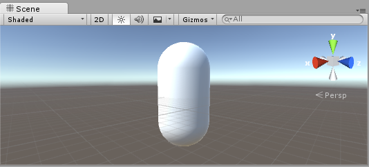
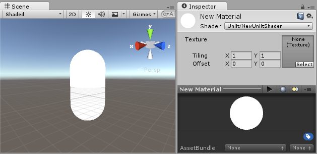
まず最初に、シェーダーのテストに使うオブジェクトを作成します。メインメニューから Game Object > 3D Object > Capsule を選択してください。それから、カメラを配置すると、カプセルが見えます。ヒエラルキー上でカプセルをダブルクリックすると、シーンビューのカプセルがフォーカスされます。それから、Main Camera オブジェクトを選択してメインメニューから Game Object > Align with View をクリックします。
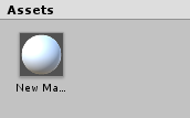
Create a new Material by selecting Create > Material from the menu in the Project View. A new material called New Material will appear in the Project View.
Creating a shader
同じように新しい シェーダー アセットを作成します。プロジェクトビューのメニューで Create > Shader > Unlit Shader を選びます。これにより、まったくライティングされていないテクスチャを表示するだけの、基本的なシェーダーが作成されます。
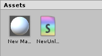
Create > Shader メニューには、この他に骨組みだけののシェーダーや、例えば基本的な サーフェスシェーダー など異なるタイプのシェーダーがあります。
Linking the mesh, material and shader
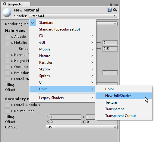
Make the material use the shader via the material’s inspector, or just drag the shader asset over the material asset in the Project View. The material inspector will display a white sphere when it uses this shader.
Now drag the material onto your mesh object in either the Scene or the Hierarchy views. Alternatively, select the object, and in the inspector make it use the material in the Mesh Renderer component’s Materials slot.
With these things set up, you can now begin looking at the shader code, and you will see the results of your changes to the shader on the capsule in the Scene View.
Main parts of the shader
To begin examining the code of the shader, double-click the shader asset in the Project View. The shader code will open in your script editor (MonoDevelop or Visual Studio).
シェーダーはこのコードで始まります。
Shader "Unlit/NewUnlitShader"
{
    Properties
    {
        _MainTex ("Texture", 2D) = "white" {}
    }
    SubShader
    {
        Tags { "RenderType"="Opaque" }
        LOD 100

        Pass
        {
            CGPROGRAM
            #pragma vertex vert
            #pragma fragment frag
            // フォグを使用します
            #pragma multi_compile_fog

            #include "UnityCG.cginc"

            struct appdata
            {
                float4 vertex : POSITION;
                float2 uv : TEXCOORD0;
            };

            struct v2f
            {
                float2 uv : TEXCOORD0;
                UNITY_FOG_COORDS(1)
                float4 vertex : SV_POSITION;
            };

            sampler2D _MainTex;
            float4 _MainTex_ST;

            v2f vert (appdata v)
            {
                v2f o;
                o.vertex = UnityObjectToClipPos(v.vertex);
                o.uv = TRANSFORM_TEX(v.uv, _MainTex);
                UNITY_TRANSFER_FOG(o,o.vertex);
                return o;
            }

            fixed4 frag (v2f i) : SV_Target
            {
                // テクスチャをサンプリング
                fixed4 col = tex2D(_MainTex, i.uv);
                // フォグを適用
                UNITY_APPLY_FOG(i.fogCoord, col);
                return col;
            }
            ENDCG
        }
    }
}
この最初のシェーダーはあまり簡単には見えませんが、心配いりません。 それぞれの部分を順に説明してゆきます。
この基本的なシェーダーの主要部分を見てみましょう。
シェーダー
Shader コマンドはシェーダーの名前の文字列を含んでいます。 シェーダーを Material インスペクターで選択するとき、スラッシュ(/) を使うとサブメニューにシェーダーを配置できます。
プロパティー
Properties ブロックには、 マテリアルの一部として保存されマテリアルインスペクターに表示される、 シェーダー変数 (テクスチャ、色など) が含まれています。 Unlit シェーダーテンプレートでは、1つのテクスチャプロパティーが宣言されています。
シェーダー
シェーダーは、1つ以上のSubShaderを持つことが可能です。 SubShader は主に、シェーダーを異なる GPU 能力に合わせて実装するために使用されます。 ここでは、SubShader についてはあまり触れないので、 例にあるすべてのシェーダーには 1つしか SubShader がありません。
パス
各 SubShader は複数の Pass で構成されています。各パスはシェーダーのマテリアルとレンダリングされるオブジェクトの頂点コードとフラグメントコードの実行を表しています。多くの単純なシェーダは 1 回のパスしか使用しませんが、ライティングと相互作用するシェーダーにはさらに多くのものが必要になる場合があります (詳細は ライティングパイプライン を参照)。Pass 内部のコマンドは通常、ブレンドモードなどの fixed の関数構文を設定します。
CGPROGRAM .. ENDCG
These keywords surround portions of Cg/HLSL code within the vertex and fragment shaders. Typically this is where most of the interesting code is. See vertex and fragment shaders for details.
Simple unlit shader
Unlit シェーダーテンプレートは、テクスチャでオブジェクトを表示するために絶対に必要なこと以外に、 さらにいくつかのことを行います。例えば、フォグのサポートや、マテリアルで Texture の Tiling/Offset フィールドの設定を行います。シェーダーについては最低限にしておいて、さらに他のコメントを加えます。
Shader "Unlit/SimpleUnlitTexturedShader"
{
    Properties
    {
        // テクスチャタイリングとテクスチャオフセットのサポートを削除します
        // そのため、マテリアルインスペクターでそれらを非表示にします
        [NoScaleOffset] _MainTex ("Texture", 2D) = "white" {}
    }
    SubShader
    {
        Pass
        {
            CGPROGRAM
            // "vert" 関数を頂点シェーダーとして使います
            #pragma vertex vert
            // "frag" 関数をピクセル (フラグメント) シェーダーとして使います
            #pragma fragment frag

            // 頂点シェーダー入力
            struct appdata
            {
                float4 vertex : POSITION; // 頂点位置
                float2 uv : TEXCOORD0; // テクスチャ座標
            };

            // vertex shader outputs ("vertex to fragment")
            struct v2f
            {
                float2 uv : TEXCOORD0; // テクスチャ座標
                float4 vertex : SV_POSITION; // クリップスペース位置
            };

            // 頂点シェーダー
            v2f vert (appdata v)
            {
                v2f o;
                // クリップスペースへの変換位置
                // (モデル*ビュー*プロジェクション行列で乗算)
                o.vertex = mul(UNITY_MATRIX_MVP, v.vertex);
                // 単にテクスチャ座標を渡します
                o.uv = v.uv;
                return o;
            }

            // サンプリングするテクスチャ
            sampler2D _MainTex;

            // ピクセルシェーダー; 低精度を返します ("fixed4" 型)
            // color ("SV_Target" セマンティック)
            fixed4 frag (v2f i) : SV_Target
            {
                // テクスチャをサンプリングして、それを返します
                fixed4 col = tex2D(_MainTex, i.uv);
                return col;
            }
            ENDCG
        }
    }
}
The Vertex Shader is a program that runs on each vertex of the 3D model. Quite often it does not do anything particularly interesting. Here we just transform vertex position from object space into so called “clip space”, which is what’s used by the GPU to rasterize the object on screen. We also pass the input texture coordinate unmodified - we’ll need it to sample the texture in the fragment shader.
フラグメントシェーダー は、オブジェクトが画面上で占めるすべてのピクセルでそれぞれ実行されるプログラムで、通常、各ピクセルの色を計算して出力するために使用されます。通常、画面上には何百万ものピクセルがあり、フラグメントシェーダはそれらのすべてに対して実行されます。 フラグメントシェーダーの最適化は、ゲームのパフォーマンス全体に関わる、きわめて重要な部分です。
Some variable or function definitions are followed by a Semantic Signifier - for example : POSITION or : SV_Target. These semantics signifiers communicate the “meaning” of these variables to the GPU. See the shader semantics page for details.
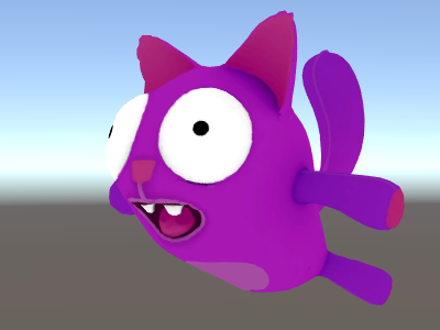
実際、適切なモデルに適切なテクスチャを使用すると、シェーダーが単純であってもなかなかよい感じに見えるものです。
Even simpler single color shader
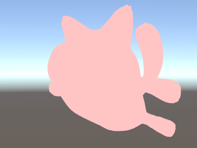
シェーダーをより単純にしましょう – すべてのオブジェクトを単色で描画するシェーダーを作成します。 これではまったく役に立たない訳ですが、ここから学習を始めましょう。
Shader "Unlit/SingleColor"
{
    Properties
    {
        // マテリアルインスペクターの Color プロパティー、デフォルトを白に
        _Color ("Main Color", Color) = (1,1,1,1)
    }
    SubShader
    {
        Pass
        {
            CGPROGRAM
            #pragma vertex vert
            #pragma fragment frag

            // 頂点シェーダー
            // 今回は、 "appdata" 構造体の代わりに、入力を手動で書き込みます
            // そして v2f 構造体を返す代わりに、1 つの出力
            // float4 のクリップ位置だけを返します
            float4 vert (float4 vertex : POSITION) : SV_POSITION
            {
                return mul(UNITY_MATRIX_MVP, vertex);
            }

            // マテリアルからのカラー
            fixed4 _Color;

            // ピクセルシェーダー、入力不要
            fixed4 frag () : SV_Target
            {
                return _Color; // 単に返します
            }
            ENDCG
        }
    }
}
This time instead of using structs for input (appdata) and output (v2f), the shader functions just spell out inputs manually. Both ways work, and which you choose to use depends on your coding style and preference.
Using mesh normals for fun and profit
Let’s proceed with a shader that displays mesh normals in world space. Without further ado:
Shader "Unlit/WorldSpaceNormals"
{
    // 今回はプロパティーはブロックしません
    SubShader
    {
        Pass
        {
            CGPROGRAM
            #pragma vertex vert
            #pragma fragment frag
            //  UnityObjectToWorldNormal ヘルパー関数を含むファイルを含みます
            #include "UnityCG.cginc"

            struct v2f {
                // 標準の ("texcoord") 補間としてワールド空間法線を出力します
                half3 worldNormal : TEXCOORD0;
                float4 pos : SV_POSITION;
            };

            // 頂点シェーダー: 入力としてオブジェクト空間法線も取ります
            v2f vert (float4 vertex : POSITION, float3 normal : NORMAL)
            {
                v2f o;
                o.pos = UnityObjectToClipPos(vertex);
                // UnityCG.cginc ファイルは、法線をオブジェクトから
                // ワールド空間に変換する関数を含みます
                o.worldNormal = UnityObjectToWorldNormal(normal);
                return o;
            }

            fixed4 frag (v2f i) : SV_Target
            {
                fixed4 c = 0;
                // 法線は、xyz 成分をもつ 3D ベクトル ; 範囲は -1..1
                // カラーとして表示するには、範囲を 0..1 にし、
                // 赤、緑、青 の成分にします。
                c.rgb = i.worldNormal*0.5+0.5;
                return c;
            }
            ENDCG
        }
    }
}
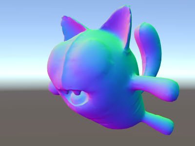
美しい色の効果に加え、法線はライティング、反射、輪郭線、その他のグラフィックス効果すべてで利用されます。
上記のシェーダーでは、 Unity のビルトインの シェーダー include ファイル の 1つを使い始めました。 ここでは、便利な関数 UnityObjectToWorldNormal を含む UnityCG.cginc を使用しました。また、頂点をオブジェクト空間から画面へ変換するユーティリティー関数 UnityObjectToClipPos も使用しました。これは単に、コードを読むのを簡単にし、ある環境下でより効率的にするためのものです。
We’ve seen that data can be passed from the vertex into fragment shader in so-called “interpolators” (or sometimes called “varyings”). In HLSL shading language they are typically labeled with TEXCOORDn semantic, and each of them can be up to a 4-component vector (see semantics page for details).
すでに法線ベクトルをカラーとして表示する簡単な方法は学んでいるので ( –1.0 から +1.0 の範囲) 、半分は乗算し、半分は加算します。他にも vertex program inputs のページに、頂点データを可視化するサンプルがいろいろあるので、参照してください。
Environment reflection using world-space normals
スカイボックス がリフレクションのソース (Lighting ウィンドウ 参照) として使われている場合、基本的にはデフォルトの リフレクションプローブ が作成され、スカイボックスのデータを内包します。リフレクションプローブは、内部的には キューブマップ テクスチャです。学習のために、前述したワールド空間の法線シェーダーを拡張します。
The code is starting to get a bit involved by now. Of course, if you want shaders that automatically work with lights, shadows, reflections and the rest of the lighting system, it’s way easier to use surface shaders. This example is intended to show you how to use parts of the lighting system in a “manual” way.
Shader "Unlit/SkyReflection"
{
    SubShader
    {
        Pass
        {
            CGPROGRAM
            #pragma vertex vert
            #pragma fragment frag
            #include "UnityCG.cginc"

            struct v2f {
                half3 worldRefl : TEXCOORD0;
                float4 pos : SV_POSITION;
            };

            v2f vert (float4 vertex : POSITION, float3 normal : NORMAL)
            {
                v2f o;
                o.pos = UnityObjectToClipPos(vertex);
                // 頂点のワールド空間位置を計算します
                float3 worldPos = mul(_Object2World, vertex).xyz;
                // ワールド空間のビュー方向を計算します
                float3 worldViewDir = normalize(UnityWorldSpaceViewDir(worldPos));
                // ワールド空間法線
                float3 worldNormal = UnityObjectToWorldNormal(normal);
                // ワールド空間レフレクションベクトル
                o.worldRefl = reflect(-worldViewDir, worldNormal);
                return o;
            }

            fixed4 frag (v2f i) : SV_Target
            {
                // デフォルトのリフレクションキューブマップをサンプリングして、リフレクションベクトルを使用します
                half4 skyData = UNITY_SAMPLE_TEXCUBE(unity_SpecCube0, i.worldRefl);
                // キューブマップデータを実際のカラーにデコードします
                half3 skyColor = DecodeHDR (skyData, unity_SpecCube0_HDR);
                // 出力します
                fixed4 c = 0;
                c.rgb = skyColor;
                return c;
            }
            ENDCG
        }
    }
}
上のサンプルでは、用意されている shader include files から、いくらかの要素を利用しています。
- ビルトインシェーダー変数 の unity_SpecCube0、unity_SpecCube0_HDR、Object2World、UNITY_MATRIX_MVP。unity_SpecCube0 はアクティブなリフレクションプローブのデータを含有します。
- UNITY_SAMPLE_TEXCUBE はキューブマップをサンプリングする ビルトインマクロ です。もっとも一般的なキューブマップは、標準の HLSL シンタックス (samplerCUBE と texCUBE) を使って宣言され使用されます。 ただし、Unity のリフレクションプローブキューブマップは、サンプラースロットで保存するために特殊な方法で宣言されます。 もし、それが何かわからない場合は、心配しなくても大丈夫です。unity_SpecCube0 キューブマップを使用するために、 UNITY_SAMPLE_TEXCUBE マクロを使用しなければならないということだけ知っておいてください。
- UnityWorldSpaceViewDir function from UnityCG.cginc, and DecodeHDR function from the same file. The latter is used to get actual color from the reflection probe data – since Unity stores reflection probe cubemap in specially encoded way.
- reflect is just a built-in HLSL function to compute vector reflection around a given normal.
Environment reflection with a normal map
Often Normal Maps are used to create additional detail on objects, without creating additional geometry. Let’s see how to make a shader that reflects the environment, with a normal map texture.
計算が かなり複雑に なってきたので、何段階かに分けて行いたいと思います。上述のシェーダーでは、リフレクションの方向は、頂点シェーダーの頂点ごとに計算され、フラグメントシェーダーはリフレクションプローブのキューブマップを参照するだけでした。ですが、法線マップを使う場合、面法線自体を各ピクセルごとに計算する必要があり、ピクセルごとに周囲の反射を計算しなくてはいけないと言う事になります。
そのため、まず最初は、いくらかの計算をフラグメントシェーダーに移すように上述のシェーダーを書き直し、ピクセル毎の計算ができるようにします。
Shader "Unlit/SkyReflection Per Pixel"
{
    SubShader
    {
        Pass
        {
            CGPROGRAM
            #pragma vertex vert
            #pragma fragment frag
            #include "UnityCG.cginc"

            struct v2f {
                float3 worldPos : TEXCOORD0;
                half3 worldNormal : TEXCOORD1;
                float4 pos : SV_POSITION;
            };

            v2f vert (float4 vertex : POSITION, float3 normal : NORMAL)
            {
                v2f o;
                o.pos = UnityObjectToClipPos(vertex);
                o.worldPos = mul(_Object2World, vertex).xyz;
                o.worldNormal = UnityObjectToWorldNormal(normal);
                return o;
            }

            fixed4 frag (v2f i) : SV_Target
            {
                // ピクセルごとのビューの方向とリフレクションベクトルを
                // 計算します
                half3 worldViewDir = normalize(UnityWorldSpaceViewDir(i.worldPos));
                half3 worldRefl = reflect(-worldViewDir, i.worldNormal);

                // 前のシェーダーと同じ
                half4 skyData = UNITY_SAMPLE_TEXCUBE(unity_SpecCube0, worldRefl);
                half3 skyColor = DecodeHDR (skyData, unity_SpecCube0_HDR);
                fixed4 c = 0;
                c.rgb = skyColor;
                return c;
            }
            ENDCG
        }
    }
}
これだけでは十分ではありません – シェーダーは、モデルの各頂点の代わりに、画面上のすべてのピクセルを計算するようになった分だけ計算量が増えて、実行速度が遅くなった以外は、まったく同じに見えます。ですが、これらの計算は無駄ではありません。多くの場合、高度に写実的なグラフィックスには、より複雑なシェーダーが必要になるのです。
さらに、ここで「接空間」について理解する必要があります。一般的に、法線マップテクスチャはモデルの「表面を覆う」座標空間上で表現されます。シェーダーでは、接空間を基準としたベクトルを取得し、テクスチャから法線ベクトルを読み込み、ワールドスペースに変換する必要があります。そしてその後、シェーダーですべての計算を行います。 さあ、やってみましょう !
Shader "Unlit/SkyReflection Per Pixel"
{
    Properties {
        // マテリアルの法線マップテクスチャ
        // デフォルトはダミーの "flat surface" 法線マップ
        _BumpMap("Normal Map", 2D) = "bump" {}
    }
    SubShader
    {
        Pass
        {
            CGPROGRAM
            #pragma vertex vert
            #pragma fragment frag
            #include "UnityCG.cginc"

            struct v2f {
                float3 worldPos : TEXCOORD0;
                // これらの 3 つのベクトルは 3x3 回転行列を格納します
                //それは接線からワールド空間に変換します
                half3 tspace0 : TEXCOORD1; // tangent.x, bitangent.x, normal.x
                half3 tspace1 : TEXCOORD2; // tangent.y, bitangent.y, normal.y
                half3 tspace2 : TEXCOORD3; // tangent.z, bitangent.z, normal.z
                // 法線マップのテクスチャ座標
                float2 uv : TEXCOORD4;
                float4 pos : SV_POSITION;
            };

            // こんどは、頂点シェーダーも頂点ごとの接線ベクトルを必要とします。
            //Unity では、接線は .w 成分を持つ  4D ベクトルで
            // bitangent ベクトルの方向を示すのに使用されます。
            // テクスチャ座標も必要です。
            v2f vert (float4 vertex : POSITION, float3 normal : NORMAL, float4 tangent : TANGENT, float2 uv : TEXCOORD0)
            {
                v2f o;
                o.pos = UnityObjectToClipPos(vertex);
                o.worldPos = mul(_Object2World, vertex).xyz;
                half3 wNormal = UnityObjectToWorldNormal(normal);
                half3 wTangent = UnityObjectToWorldDir(tangent.xyz);
                // 法線と接線を合わせたものから bitangent を計算します
                half tangentSign = tangent.w * unity_WorldTransformParams.w;
                half3 wBitangent = cross(wNormal, wTangent) * tangentSign;
                // 接線空間マトリクス行列を出力します
                o.tspace0 = half3(wTangent.x, wBitangent.x, wNormal.x);
                o.tspace1 = half3(wTangent.y, wBitangent.y, wNormal.y);
                o.tspace2 = half3(wTangent.z, wBitangent.z, wNormal.z);
                o.uv = uv;
                return o;
            }

            // シェーダープロパティーの法線マップテクスチャ
            sampler2D _BumpMap;

            fixed4 frag (v2f i) : SV_Target
            {
                // 法線マップをサンプリングして Unity エンコーディングからデコードします
                half3 tnormal = UnpackNormal(tex2D(_BumpMap, i.uv));
                // 法線を接線からワールド空間に変換します
                half3 worldNormal;
                worldNormal.x = dot(i.tspace0, tnormal);
                worldNormal.y = dot(i.tspace1, tnormal);
                worldNormal.z = dot(i.tspace2, tnormal);

                // 残りは前のシェーダーと同じ
                half3 worldViewDir = normalize(UnityWorldSpaceViewDir(i.worldPos));
                half3 worldRefl = reflect(-worldViewDir, worldNormal);
                half4 skyData = UNITY_SAMPLE_TEXCUBE(unity_SpecCube0, worldRefl);
                half3 skyColor = DecodeHDR (skyData, unity_SpecCube0_HDR);
                fixed4 c = 0;
                c.rgb = skyColor;
                return c;
            }
            ENDCG
        }
    }
}
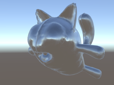
やれやれ、非常に難解でした。ですが見てください、反射に法線マップが適用されています !
Adding more textures
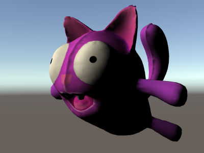
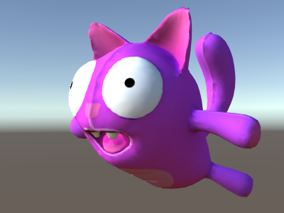
法線マップを加味して空を反射するようになったシェーダーに、さらにテクスチャを追加していきましょう。最初の照明無しのサンプルで用いたベースカラーのテクスチャと、窪みを暗くするためのオクルージョンを追加します。
Shader "Unlit/More Textures"
{
    Properties {
        // マテリアル内で 3 テクスチャを使います
        _MainTex("Base texture", 2D) = "white" {}
        _OcclusionMap("Occlusion", 2D) = "white" {}
        _BumpMap("Normal Map", 2D) = "bump" {}
    }
    SubShader
    {
        Pass
        {
            CGPROGRAM
            #pragma vertex vert
            #pragma fragment frag
            #include "UnityCG.cginc"

            // 前のシェーダーと完全に同じです
            struct v2f {
                float3 worldPos : TEXCOORD0;
                half3 tspace0 : TEXCOORD1;
                half3 tspace1 : TEXCOORD2;
                half3 tspace2 : TEXCOORD3;
                float2 uv : TEXCOORD4;
                float4 pos : SV_POSITION;
            };
            v2f vert (float4 vertex : POSITION, float3 normal : NORMAL, float4 tangent : TANGENT, float2 uv : TEXCOORD0)
            {
                v2f o;
                o.pos = UnityObjectToClipPos(vertex);
                o.worldPos = mul(_Object2World, vertex).xyz;
                half3 wNormal = UnityObjectToWorldNormal(normal);
                half3 wTangent = UnityObjectToWorldDir(tangent.xyz);
                half tangentSign = tangent.w * unity_WorldTransformParams.w;
                half3 wBitangent = cross(wNormal, wTangent) * tangentSign;
                o.tspace0 = half3(wTangent.x, wBitangent.x, wNormal.x);
                o.tspace1 = half3(wTangent.y, wBitangent.y, wNormal.y);
                o.tspace2 = half3(wTangent.z, wBitangent.z, wNormal.z);
                o.uv = uv;
                return o;
            }

            // シェーダープロパティーのテクスチャ
            sampler2D _MainTex;
            sampler2D _OcclusionMap;
            sampler2D _BumpMap;

            fixed4 frag (v2f i) : SV_Target
            {
                // 前のシェーダーと同じです...
                half3 tnormal = UnpackNormal(tex2D(_BumpMap, i.uv));
                half3 worldNormal;
                worldNormal.x = dot(i.tspace0, tnormal);
                worldNormal.y = dot(i.tspace1, tnormal);
                worldNormal.z = dot(i.tspace2, tnormal);
                half3 worldViewDir = normalize(UnityWorldSpaceViewDir(i.worldPos));
                half3 worldRefl = reflect(-worldViewDir, worldNormal);
                half4 skyData = UNITY_SAMPLE_TEXCUBE(unity_SpecCube0, worldRefl);
                half3 skyColor = DecodeHDR (skyData, unity_SpecCube0_HDR);
                fixed4 c = 0;
                c.rgb = skyColor;

                // ベーステクスチャとオクルージョンマップで空の色を調整します
                fixed3 baseColor = tex2D(_MainTex, i.uv).rgb;
                fixed occlusion = tex2D(_OcclusionMap, i.uv).r;
                c.rgb *= baseColor;
                c.rgb *= occlusion;

                return c;
            }
            ENDCG
        }
    }
}
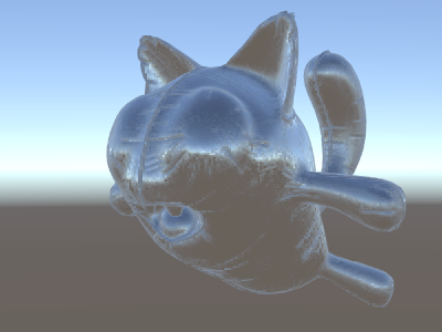
バルーンの猫の見栄えが良くなりました !

Texturing shader examples
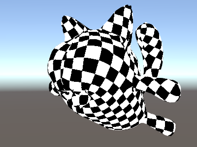
Procedural checkerboard pattern
これは、メッシュのテクスチャ座標を基準にして市松模様を出力するシェーダーです:
Shader "Unlit/Checkerboard"
{
    Properties
    {
        _Density ("Density", Range(2,50)) = 30
    }
    SubShader
    {
        Pass
        {
            CGPROGRAM
            #pragma vertex vert
            #pragma fragment frag
            #include "UnityCG.cginc"

            struct v2f
            {
                float2 uv : TEXCOORD0;
                float4 vertex : SV_POSITION;
            };

            float _Density;

            v2f vert (float4 pos : POSITION, float2 uv : TEXCOORD0)
            {
                v2f o;
                o.vertex = UnityObjectToClipPos(pos);
                o.uv = uv * _Density;
                return o;
            }

            fixed4 frag (v2f i) : SV_Target
            {
                float2 c = i.uv;
                c = floor(c) / 2;
                float checker = frac(c.x + c.y) * 2;
                return checker;
            }
            ENDCG
        }
    }
}
The density slider in the Properties block controls how dense the checkerboard is. In the vertex shader, the mesh UVs are multiplied by the density value to take them from a range of 0 to 1 to a range of 0 to density. Let’s say the density was set to 30 - this will make i.uv input into the fragment shader contain floating point values from zero to 30 for various places of the mesh being rendered.
Then the fragment shader code takes only the integer part of the input coordinate using HLSL’s built-in floor function, and divides it by two. Recall that the input coordinates were numbers from 0 to 30; this makes them all be “quantized” to values of 0, 0.5, 1, 1.5, 2, 2.5, and so on. This was done on both the x and y components of the input coordinate.
Next up, we add these x and y coordinates together (each of them only having possible values of 0, 0.5, 1, 1.5, …) and only take the fractional part using another built-in HLSL function, frac. Result of this can only be either 0.0 or 0.5. We then multiply it by two to make it either 0.0 or 1.0, and output as a color (this results in black or white color respectively).
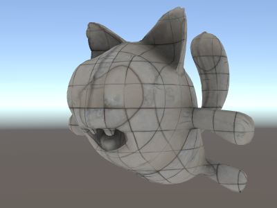
Tri-planar texturing
プロシージャル、もしくは複雑なメッシュでは、通常の UV 座標を用いたテクスチャ設定の代わりに、オブジェクトに 3 方向からの “project” テクスチャを使った方がやりやすい事があります。これは “tri-planar” テクスチャ法と呼ばれます。面法線を 3 方向からのテクスチャの重み付けに使うという考え方です。シェーダーはこのようになります:
Shader "Unlit/Triplanar"
{
    Properties
    {
        _MainTex ("Texture", 2D) = "white" {}
        _Tiling ("Tiling", Float) = 1.0
        _OcclusionMap("Occlusion", 2D) = "white" {}
    }
    SubShader
    {
        Pass
        {
            CGPROGRAM
            #pragma vertex vert
            #pragma fragment frag
            #include "UnityCG.cginc"

            struct v2f
            {
                half3 objNormal : TEXCOORD0;
                float3 coords : TEXCOORD1;
                float2 uv : TEXCOORD2;
                float4 pos : SV_POSITION;
            };

            float _Tiling;

            v2f vert (float4 pos : POSITION, float3 normal : NORMAL, float2 uv : TEXCOORD0)
            {
                v2f o;
                o.pos = UnityObjectToClipPos(pos);
                o.coords = pos.xyz * _Tiling;
                o.objNormal = normal;
                o.uv = uv;
                return o;
            }

            sampler2D _MainTex;
            sampler2D _OcclusionMap;

            fixed4 frag (v2f i) : SV_Target
            {
                // テクスチャウェイトには法線の絶対値を使います
                half3 blend = abs(i.objNormal);
                // ウェイトの合計は 1 までということに気を付けます (x+y+z の合計で割り算されます)
                blend /= dot(blend,1.0);
                //  x,y,z 軸の 3 つのテクスチャプロジェクションを読み込みます
                fixed4 cx = tex2D(_MainTex, i.coords.yz);
                fixed4 cy = tex2D(_MainTex, i.coords.xz);
                fixed4 cz = tex2D(_MainTex, i.coords.xy);
                // ウェイトに基づいてテクスチャをブレンドします
                fixed4 c = cx * blend.x + cy * blend.y + cz * blend.z;
                // 標準オクルージョンマップで変更します
                c *= tex2D(_OcclusionMap, i.uv);
                return c;
            }
            ENDCG
        }
    }
}
Calculating lighting
一般的に、Unity のライティングパイプラインのためのシェーダーが必要な場合、 サーフェスシェーダー を書きます。 サーフェスシェーダーは、「厄介な分部」のほとんどをかたずけてくれます。実際にシェーダーコードで書かなければならないのは、サーフェスプロパティーの宣言だけです。
ただし、場合によって、標準サーフェスシェーダーパスを避けた方がよい場合があります。 それは、パフォーマンスに関する理由で、全体のライティングパイプラインの限られたサブセットだけをサポートしたい場合か、 または、あまり「標準ライティング」ではないカスタム化したものを実行したい場合、いずれかです。 以下の例で、手動で書いた頂点、およびフラグメントシェーダーからどのようにライティングデータに働きかけるかを説明します。 サーフェスシェーダーによって (シェーダーインスペクター で) 生成されたコードを見ることもまた、 よい学習リソースです。
Simple diffuse lighting
The first thing we need to do is to indicate that our shader does in fact need lighting information passed to it. Unity’s rendering pipeline supports various ways of rendering; here we’ll be using the default forward rendering one.
We’ll start by only supporting one directional light. Forward rendering in Unity works by rendering the main directional light, ambient, lightmaps and reflections in a single pass called ForwardBase. In the shader, this is indicated by adding a pass tag: Tags {“LightMode”=“ForwardBase”}. This will make directional light data be passed into shader via some built-in variables.
これは、頂点単位の拡散反射光を計算し、テクスチャを 1 枚だけ使う、簡単なシェーダーです:
Shader "Lit/Simple Diffuse"
{
    Properties
    {
        [NoScaleOffset] _MainTex ("Texture", 2D) = "white" {}
    }
    SubShader
    {
        Pass
        {
            // pass はフォワードレンダリングパイプラインの「ベース」パスで
            // あることを示します。アンビエントと主要ディレクショナルライトの
            // データ設定を行います。ライト方向は _WorldSpaceLightPos0
            // カラーは _LightColor0
            Tags {"LightMode"="ForwardBase"}

            CGPROGRAM
            #pragma vertex vert
            #pragma fragment frag
            #include "UnityCG.cginc" //  UnityObjectToWorldNormal に対し
            #include "UnityLightingCommon.cginc" // _LightColor0 に対し

            struct v2f
            {
                float2 uv : TEXCOORD0;
                fixed4 diff : COLOR0; // 拡散ライティングカラー
                float4 vertex : SV_POSITION;
            };

            v2f vert (appdata_base v)
            {
                v2f o;
                o.vertex = UnityObjectToClipPos(v.vertex);
                o.uv = v.texcoord;
                // ワールド空間で頂点法線を取得
                half3 worldNormal = UnityObjectToWorldNormal(v.normal);
                // 標準拡散 (Lambert) ライティングを求めるための
                //法線とライト方向間のドット積
                half nl = max(0, dot(worldNormal, _WorldSpaceLightPos0.xyz));
                // ライトカラーの積
                o.diff = nl * _LightColor0;
                return o;
            }

            sampler2D _MainTex;

            fixed4 frag (v2f i) : SV_Target
            {
                // テクスチャのサンプリング
                fixed4 col = tex2D(_MainTex, i.uv);
                // ライティングで乗算します
                col *= i.diff;
                return col;
            }
            ENDCG
        }
    }
}
これによってオブジェクトにライトの方向が反映するようになります - ライト方向に向いている部分が光り、反対を向いている部分は、全く光りません。
Diffuse lighting with ambient
上記の例ではアンビエントライティングやライトプローブが考慮されていません。修正しましょう! 1 行のコードを追加することでこれが可能です。アンビエントと ライトプローブ のデータは球面調和関数の形でシェーダーに渡され、UnityCG.cginc include ファイル の ShadeSH9 関数はワールド空間法線を前提として、それを評価する作業すべてを行います。
Shader "Lit/Diffuse With Ambient"
{
    Properties
    {
        [NoScaleOffset] _MainTex ("Texture", 2D) = "white" {}
    }
    SubShader
    {
        Pass
        {
            Tags {"LightMode"="ForwardBase"}

            CGPROGRAM
            #pragma vertex vert
            #pragma fragment frag
            #include "UnityCG.cginc"
            #include "UnityLightingCommon.cginc"

            struct v2f
            {
                float2 uv : TEXCOORD0;
                fixed4 diff : COLOR0;
                float4 vertex : SV_POSITION;
            };

            v2f vert (appdata_base v)
            {
                v2f o;
                o.vertex = UnityObjectToClipPos(v.vertex);
                o.uv = v.texcoord;
                half3 worldNormal = UnityObjectToWorldNormal(v.normal);
                half nl = max(0, dot(worldNormal, _WorldSpaceLightPos0.xyz));
                o.diff = nl * _LightColor0;

                // 前のシェーダーとくらべ、唯一の相違点
                // 主要ライトの拡散ライティングに加え
                // アンビエントやライトプローブの照明を加えます。
                // UnityCG.cginc の ShadeSH9 関数がワールド空間法線で
                // それを評価します。
                o.diff.rgb += ShadeSH9(half4(worldNormal,1));
                return o;
            }

            sampler2D _MainTex;

            fixed4 frag (v2f i) : SV_Target
            {
                fixed4 col = tex2D(_MainTex, i.uv);
                col *= i.diff;
                return col;
            }
            ENDCG
        }
    }
}
このシェーダーは実際のところ、用意されている Legacy Diffuse シェーダーにとてもよく似てきました !
Implementing shadow casting
Our shader currently can neither receive nor cast shadows. Let’s implement shadow casting first.
In order to cast shadows, a shader has to have a ShadowCaster pass type in any of its subshaders or any fallback. The ShadowCaster pass is used to render the object into the shadowmap, and typically it is fairly simple - the vertex shader only needs to evaluate the vertex position, and the fragment shader pretty much does not do anything. The shadowmap is only the depth buffer, so even the color output by the fragment shader does not really matter.
これは、多くのシェーダーで同様です。シャドウキャスターのパスは大体いつも同じになります (オブジェクトが、カスタムの頂点シェーダーに基づいて変形したり、カットアウトのアルファを使った半透明部分が有ったりする場合を除く)。シェーダーコマンド UsePass で使いまわすのが、最も簡単な方法です。
Pass
{
    // regular lighting pass
}
// VertexLit ビルトインシェーダーのshadow caster を取得
UsePass "Legacy Shaders/VertexLit/SHADOWCASTER"
ですが、今は学習の途中なので、同じことをいわゆる「手動で」行いましょう。コードを短くするために、 ライティングのパス (ForwardBase) を、テクスチャを使わないアンビエントのみのコードに置き換えました。その下に、オブジェクトがシャドウキャスティングできるようにするための ShadowCaster のパスがあります。
Shader "Lit/Shadow Casting"
{
    SubShader
    {
        // とても簡易なライティングパス。テクスチャでないアンビエントを行います
        Pass
        {
            Tags {"LightMode"="ForwardBase"}
            CGPROGRAM
            #pragma vertex vert
            #pragma fragment frag
            #include "UnityCG.cginc"
            struct v2f
            {
                fixed4 diff : COLOR0;
                float4 vertex : SV_POSITION;
            };
            v2f vert (appdata_base v)
            {
                v2f o;
                o.vertex = UnityObjectToClipPos(v.vertex);
                half3 worldNormal = UnityObjectToWorldNormal(v.normal);
                // アンビエントのみを評価します
                o.diff.rgb = ShadeSH9(half4(worldNormal,1));
                o.diff.a = 1;
                return o;
            }
            fixed4 frag (v2f i) : SV_Target
            {
                return i.diff;
            }
            ENDCG
        }

        // shadow caster レンダリングパス。UnityCG.cginc のマクロを使って
        // 手動で実装されます。
        Pass
        {
            Tags {"LightMode"="ShadowCaster"}

            CGPROGRAM
            #pragma vertex vert
            #pragma fragment frag
            #pragma multi_compile_shadowcaster
            #include "UnityCG.cginc"

            struct v2f {
                V2F_SHADOW_CASTER;
            };

            v2f vert(appdata_base v)
            {
                v2f o;
                TRANSFER_SHADOW_CASTER_NORMALOFFSET(o)
                return o;
            }

            float4 frag(v2f i) : SV_Target
            {
                SHADOW_CASTER_FRAGMENT(i)
            }
            ENDCG
        }
    }
}
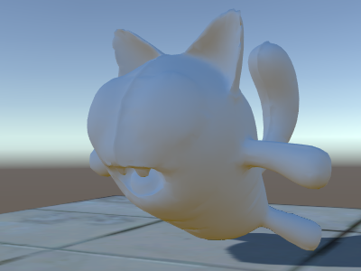
さて、下の方に飛行機があります。標準ビルトイン拡散シェーダーを使用しているので、 シャドウが実行されているのがわかります (現在使用しているシェーダーは、シャドウを 受けることを まだサポートしていないことを覚えておいてください)。
ここでは #pragma multi_compile_shadowcaster ディレクティブを使用しました。これにより、シェーダーはそれぞれ定義された様々なプリプロセッサーマクロと一緒にいくつかのバリアントにコンパイルされます。 (詳細は、複数のシェーダープログラムのバリアントを作る を参照)。シャドウマップにレンダリングするとき、「ポイントライト」と「他のライトタイプ」の場合は、少し違うシェーダーコードが必要です。そのため、このディレクティブが必要です。
Receiving shadows
シャドウを受けるためのサポートを実装するには、基本ライティングパスを数種のバリアントにコンパイルし、 「シャドウのないディレクショナライト」と「シャドウのあるディレクショナライト」 を適切に処理します。 #pragma multi_compile_fwdbase ディレクティブによって、これを実行できます (詳細は、複数のシェーダープログラムのバリアントを作る を参照してください)。実際は、そのディレクティブは、もっとたくさんのことを行います。 リアルタイム GI のオン/オフ、その他、異なるタイプのライトマップ向けのバリアントもコンパイルします。現状、その全てが必要な訳では無いので、それらのバリアントはスキップしてしまって問題ありません。
Then to get actual shadowing computations, we’ll #include “AutoLight.cginc” shader include file and use SHADOW_COORDS, TRANSFER_SHADOW, SHADOW_ATTENUATION macros from it.
これが、シェーダーです。
Shader "Lit/Diffuse With Shadows"
{
    Properties
    {
        [NoScaleOffset] _MainTex ("Texture", 2D) = "white" {}
    }
    SubShader
    {
        Pass
        {
            Tags {"LightMode"="ForwardBase"}
            CGPROGRAM
            #pragma vertex vert
            #pragma fragment frag
            #include "UnityCG.cginc"
            #include "Lighting.cginc"

            // シャドウあり、シャドウなしで複数のバリアントにシェーダーをコンパイルします
            // (まだ、ライトマップを考えるひつようはありません。このバリアントを飛ばします)
            #pragma multi_compile_fwdbase nolightmap nodirlightmap nodynlightmap novertexlight
            // shadow helper 関数とマクロ
            #include "AutoLight.cginc"

            struct v2f
            {
                float2 uv : TEXCOORD0;
                SHADOW_COORDS(1) // シャドウのデータを TEXCOORD1 に格納
                fixed3 diff : COLOR0;
                fixed3 ambient : COLOR1;
                float4 pos : SV_POSITION;
            };
            v2f vert (appdata_base v)
            {
                v2f o;
                o.pos = UnityObjectToClipPos(v.vertex);
                o.uv = v.texcoord;
                half3 worldNormal = UnityObjectToWorldNormal(v.normal);
                half nl = max(0, dot(worldNormal, _WorldSpaceLightPos0.xyz));
                o.diff = nl * _LightColor0.rgb;
                o.ambient = ShadeSH9(half4(worldNormal,1));
                // シャドウのデータを計算します
                TRANSFER_SHADOW(o)
                return o;
            }

            sampler2D _MainTex;

            fixed4 frag (v2f i) : SV_Target
            {
                fixed4 col = tex2D(_MainTex, i.uv);
                // シャドウの減衰を計算します (1.0 = 完全に照射される, 0.0 = 完全に影になる)
                fixed shadow = SHADOW_ATTENUATION(i);
                // シャドウでライトの照明を暗くします。アンビエントをそのまま保ちます
                fixed3 lighting = i.diff * shadow + i.ambient;
                col.rgb *= lighting;
                return col;
            }
            ENDCG
        }

        // 投影サポート
        UsePass "Legacy Shaders/VertexLit/SHADOWCASTER"
    }
}
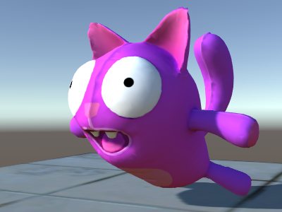
見てください、今度は影ができました。
Other shader examples
Fog
Shader "Custom/TextureCoordinates/Fog" {
    SubShader {
        Pass {
            CGPROGRAM
            #pragma vertex vert
            #pragma fragment frag

            //fog がコンパイルされるのに必要です
            #pragma multi_compile_fog

            #include "UnityCG.cginc"

            struct vertexInput {
                float4 vertex : POSITION;
                float4 texcoord0 : TEXCOORD0;
            };

            struct fragmentInput{
                float4 position : SV_POSITION;
                float4 texcoord0 : TEXCOORD0;

                //fog の量を渡すために使用されます。数は自由なtexcoord
                UNITY_FOG_COORDS(1)
            };

            fragmentInput vert(vertexInput i){
                fragmentInput o;
                o.position = UnityObjectToClipPos(i.vertex);
                o.texcoord0 = i.texcoord0;

                //クリップスペース位置の fog の量を渡すために使用
                UNITY_TRANSFER_FOG(o,o.position);
                return o;
            }

            fixed4 frag(fragmentInput i) : SV_Target {
                fixed4 color = fixed4(i.texcoord0.xy,0,0);

                // fog (追加パスは自動的に処理されます) を適用
                UNITY_APPLY_FOG(i.fogCoord, color);

                //カスタムの fog の色を処理するために、他のオプションは
                //#ifdef UNITY_PASS_FORWARDADD
                //  UNITY_APPLY_FOG_COLOR(i.fogCoord, color, float4(0,0,0,0));
                //#else
                //  fixed4 myCustomColor = fixed4(0,0,1,0);
                //  UNITY_APPLY_FOG_COLOR(i.fogCoord, color, myCustomColor);
                //#endif

                return color;
            }
            ENDCG
        }
    }
}
You can download the examples shown above as a zipped Unity project.