Warning
Warning: Unity Simulation is deprecated as of December 2023, and is no longer available.
Set up an Ackermann controller
Now that our Ackermann vehicle model is in the scene, we want to add the corresponding controller.
What is an Ackermann steering drive?
Ackermann steering is used in car-like vehicles. The basic idea consists of rotating the inner wheel slightly sharper than the outer wheel to reduce tire slippage.
The Ackermann controller operates any number of axles which can be powered and/or steered. Vehicles like cars and forklifts are harder to control because they cannot rotate in place. Think about how parallel parking requires planning and foresight in order to get into the right position and orientation!
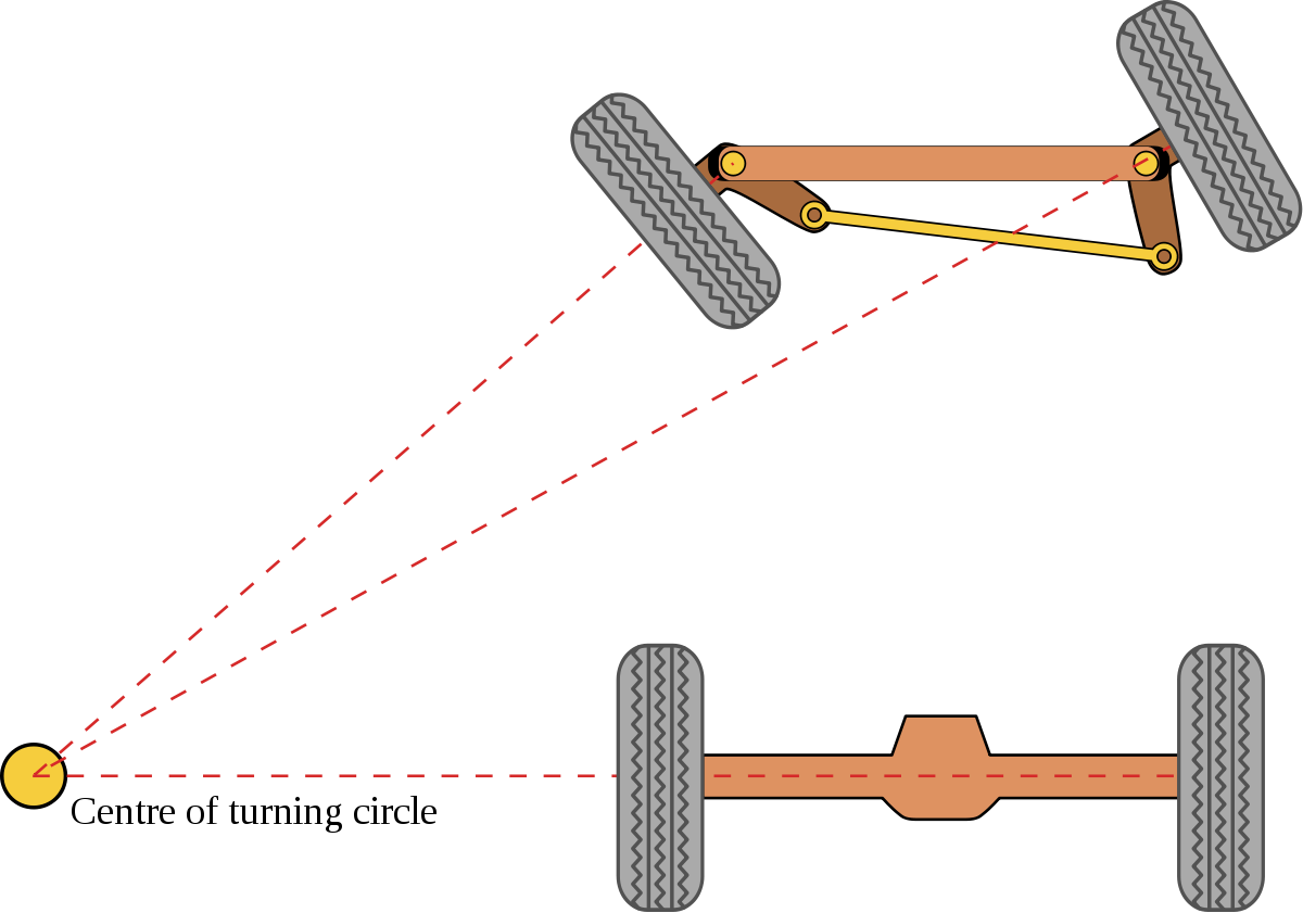

Based on this simple concept, the message schema uses the idea of a singular imaginary middle wheel for each axle that defines the turning circle. The inner and outer wheel rotations are then adjusted accordingly to match that turning circle center.
Interface
ROS Message
float32 steering_angle          # desired virtual angle (radians)
float32 steering_angle_velocity # desired rate of change (radians/s)

float32 speed                   # desired forward speed (units/s)
float32 acceleration            # desired acceleration (units/s^2)
float32 jerk                    # desired jerk (units/s^3)
C# Interface
using System;

namespace Unity.Simulation.VehicleControllers
{
    [Serializable]
    public struct AckermannControlMessage
    {
        public float steeringAngle;         // desired virtual angle (radians)
        public float steeringAngleVelocity; // desired rate of change (radians/s)
        public float speed;                 // desired forward speed (meters/s)
        public float acceleration;          // desired acceleration (meters/s^2)
        public float jerk;                  // desired jerk (meters/s^3)

        public override string ToString()
        {
            return $"(SteeringAngle: {steeringAngle}, SteeringAngleVelocity: {steeringAngleVelocity}, Speed: {speed}, Acceleration: {acceleration}, Jerk: {jerk})";
        }
    }
}
Warning
Units of measurement
Pay attention to the units of measurement in your C# implementation. While the ROS message is unit-agnostic, Unity uses meters as the default unit of measurement. Therefore, the message accepts meters for the linear velocity and its derivatives. The steering angle and velocity is measured in radians and radians per second. Keep in mind, though, that the pre-made keyboard adapter will accept degrees and degrees per second as input for those properties, as it is easier to conceptualize!
The drive interface accepts both steering_angle and steering_angle_velocity and passes them on to the ArticulationDrive position and velocity setpoints. The ArticulationDrive implements PD control on both setpoints. If you would like to use only the position or velocity control, set the associated P gain to zero to disable that drive.
- steering_angle. The angular rotation of the steering column (the imaginary middle wheel). In this model, it is sent directly to the specified ArticulationBody components defined in the AckermannAxle components of the Ackermann Controller. It then sets the ArticulationDrive angular position setpoints for the arms and wheels for each steer axle. Positive values assume a clockwise direction looking from the top downwards to the car.
- steering_angle_velocity. The speed at which the given steering_angle is reached. In this model, it is used to define the interpolation of position towards the target.
- speed. This is the vehicle's desired linear speed. In this model, it is sent directly to the wheel's ArticulationDrive's velocity setpoint. Positive speed will move the wheels towards the direction defined in the Local Forward Direction field.
- acceleration. The acceleration variable is used to interpolate the desired linear speed of the robot.
- jerk. The jerk variable is used to interpolate the desired acceleration of the robot.
The maximum limits for each axis of movement can be set by using the Authoring script or simply by going to each ArticulationBody and changing the upper and lower limits on the ArticulationDrive.
Now let's add some C# components!
Add the following components to the root GameObject of your robot:
- AckermannController
- AckermannKeyboardAdapter OR AckermannROSAdapter - Choose an adapter according to how you intend to control the robot.
- AckermannAuthoring
And lastly, we need to set up the AckermannAxle components.
Each pair of wheels on your robot will be governed by a single AckermannAxle component. Right now the only thing to keep in mind is, whether the pair of wheels will be responsible for turning your robot or not.
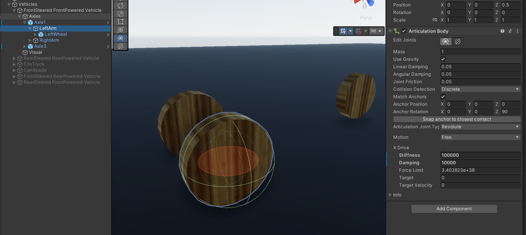
In the case where they will be turning, you will need to add an intermediary ArticulationBody component with a revolute joint that is rotated perpendicular to the driving plane.
We will be over the axle fields in more detail in the next section.
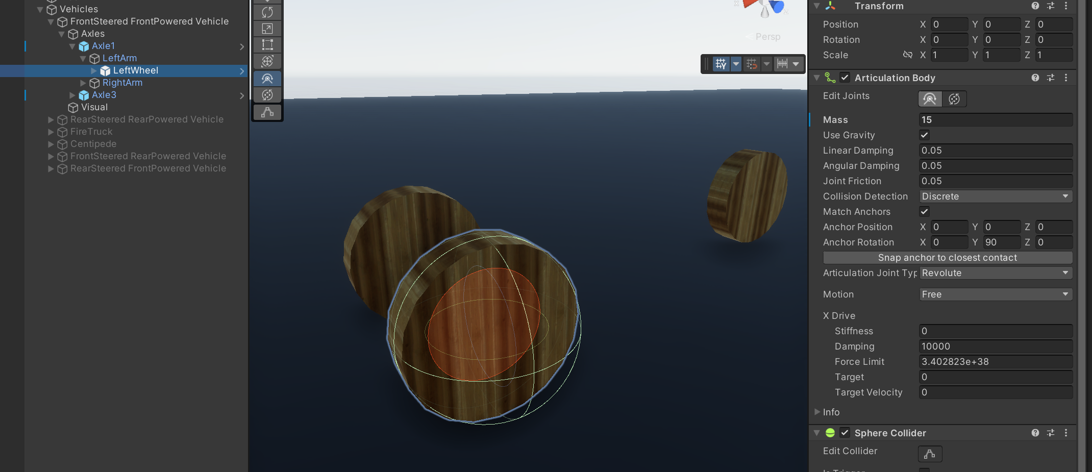
One thing to keep in mind is that your wheels should be using Sphere Colliders, even though their visual shape might be a cylinder. This will improve results of the physics simulation and the ability of the robot to reach target setpoints.
Configurable parameters
Controller
Drag the corresponding wheel links to the fields on the controller. The Ackermann controller consists of two driving rear wheels and any number of pairs of caster wheels in the front.
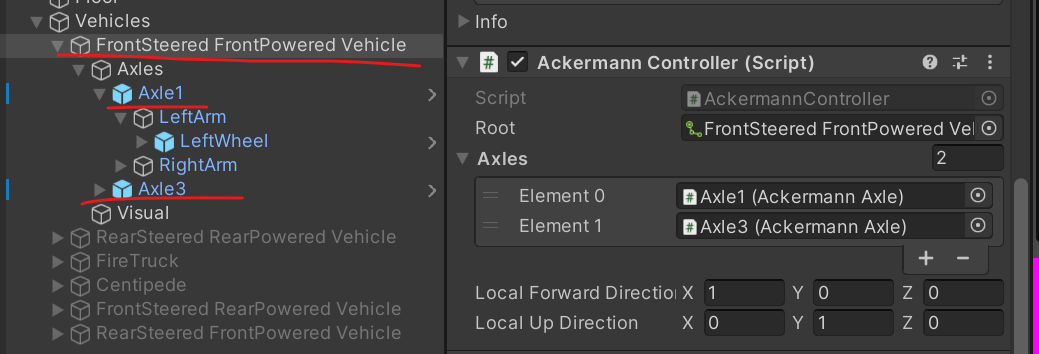
- Root - this should be the first ArticulationBody in your chain; the topmost parent.
- Axles - these should be the AckermannAxle components that are responsible for turning and powering the wheels.
- Local Forward Direction - a direction vector that specifies which way the vehicle is facing. Meaning driving forward will move the vehicle in that direction. The direction is local to the root Articulation Body of the chain! This is used to determine the if the vehicle is front steered or rear steered.
- Local Up Direction - This defines what direction is "Up" for your robot. It may be used to determine which wheel is the "Left" or "Right" one when trying to automatically find other components from the Axle component. For most cases this should be left as the default value.
Ackermann Axle

- Left and Right Wheels - These are the revolute joint ArticulationBodies that are perpendicular to the ground plane and on which the whole robot moves.
- Left and Right Arms - These are optional revolute joint ArticulationBody components which are paralell to the ground plane and are used to rotate the wheels when driving the robot. Leave these empty if the axle is not steered.
If an axle is:
- Steered - it will need a "Left Arm" and a "Right Arm" intermediary ArticulationBody that will be used to rotate the wheel based on the message that the vehicle controller receives.
- Powered - it will contribute to making the wheels go forward/backward when the vehicle controller receives a message with a direction to move in. The "Left Arm" and "Right Arm" components can be ignored as they will not be used.
- Neither powered, nor steered - the wheels on this axle will not contribute to moving the vehicle. The "Left Arm" and "Right Arm" fields can be ignored. The wheel fields should still be filled since their properties will be used. Usually these would be the caster wheels of a robot.
The Find all components button will try to automatically locate the arm and wheel ArticulationBodies within the axle children. It uses the local forward and local up directions to figure out which wheel/arm is the left or the right one. Keep in mind that this button might not work for your set up so you still might have to set the fields manually.
Keyboard Adapter
If you chose to use the Keyboard Adapter, adjust the max steering angle, the steering velocity (this is the velocity that the wheels will reach when rotating to the desired rotation), max linear velocity, linear acceleration, and jerk. Linear speeds are measured in meters per second, while steering velocity is in degrees per second.
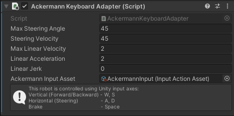
- Max Steering Angle - the maximum angle that the imaginary wheel of the outermost steering axle will try to reach (While both left and right wheels will be adjusted slightly to match this), measured in degrees. All the other axles will be derived to match their own respective rotations on the imaginary circle of rotation.
- Steering velocity - the speed at which the steered axle arms will try to rotate at, measured in degrees per second.
- Max Linear Velocity - the maximum linear velocity that the vehicle will try to move at, measured in meters per second.
- Linear Acceleration - the rate of change of velocity, or how fast will the robot accelerate, measured in meters per second squared. A value of 0 is interpreted as an instant change.
- Linear Jerk - the rate of change of acceleration, measured in meters per second cubed. A value of 0 is interpreted as an instant change.
- Ackermann Input Asset - the InputActionAsset which will be used to capture input from the keyboard. You can find a working example asset for this in the Vehicle-ControllerSampleScenes sample attached with the package.
Connector adapter

If you are using the Connector adapter, you can set the topic, which the connection will try to use to subscribe to the message.
Authoring
Let's move onto the Ackermann Authoring script. It is an optional script that makes it easier to set up all the relevant ArticulationBody parameters of your robot.
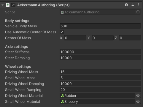
- Vehicle Body Mass. The mass of the root of the body measured in kilograms.
- Automatic Center Of Mass and Center Of Mass. Change the center of mass to fit your robot or leave it as Automatic. When set to use Automatic, the Center of Mass will be calculated based on the Articulation Bodies and their colliders.
- Steer Stiffness and Damping. Stiffness is the strength of the spring that tries to reach the target position setpoint on the steering axle, while damping controls the velocity-damping effect of the spring. Damping also controls how fast the ArticulationDrive tries to reach the target velocity setpoint. These values are set for the ArticulationDrives of each body and not for the ArticulationBodies themselves! For a more in-depth explanation on how the ArticulationDrive reaches its targets, read more in the ArticulationBody Manual page
- Driving and small wheel masses. The higher the driving wheel mass, the better results it will have when trying to reach the given target velocity. In other words, if you imported your vehicle model using URDF-Composer, such that you're using the wheel masses specified by your URDF, and you're finding that the vehicle isn't reaching its target velocity, try increasing the wheel masses by 2x or 3x (not 50x or 100x). The small wheel mass has less of an impact on the simulation.
- Driving wheel Damping. The strength of the spring that tries to reach the given target-velocity setpoint. This will set the Damping term on both driving wheel ArticulationDrives. This value is set for the ArticulationDrive of each of the bodies and not for the ArticulationBodies themselves! For a more in-depth explanation on how the ArticulationDrive reaches its targets, read more in the ArticulationBody Manual page
- Small wheel Damping. It's good to use some non-zero value to reduce caster wheel oscillation during the simulation. This property is NOT set for the Damping values of the ArticulationBody itself, but for the ArticulationDrive within the body component.
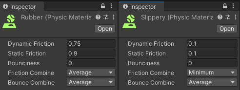
- Wheel Materials. These are Unity Physic Material objects, which can be created by right-clicking on the Project window -> Create -> Physic Material. The driving wheels should have a higher-friction material and the caster wheels should have a very slippery one.
Congratulations! You should now have an Ackermann Drive robot that is controlled either by keyboard or by sending ROS messages!