Warning
Warning: Unity Simulation is deprecated as of December 2023, and is no longer available.
Set up a three-wheel controller
If you have a three-wheeled vehicle model in your Scene, you can add this corresponding controller.
What is a three-wheeled robot?
In this particular case, we are talking about a vehicle with a single driving wheel that can be rotated and two supporting caster wheels. It is very similar to the Ackermann drive vehicle, but instead of having one imaginary middle wheel and calculated angles for two physical driving wheels, we have just one physical driving wheel in the middle.
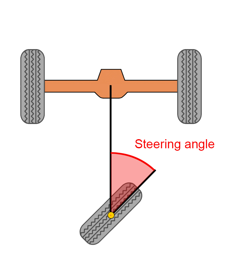
The robot can rotate the middle wheel and drive the vehicle this way. Like a four-wheeled Ackermann vehicle, this robot is non-holonomic, so some extra trajectory planning will be required. You won't be able to move directly sideways, for example.
Interface
The interface uses the same message as the Ackermann drive controller.
ROS Message
float32 steering_angle          # desired steering angle (radians)
float32 steering_angle_velocity # desired rate of change (radians/s)

float32 speed                   # desired forward speed (units/s)
float32 acceleration            # desired acceleration (units/s^2)
float32 jerk                    # desired jerk (units/s^3)
C# Interface
using System;
using UnityEngine;

namespace Unity.Simulation.VehicleControllers
{
    [Serializable]
    public struct ThreeWheelControlMessage
    {
        public float steeringAngle;         // desired steering angle (radians)
        public float steeringAngleVelocity; // desired rate of change (radians/s)
        public float speed;                 // desired forward speed (m/s)
        public float acceleration;          // desired acceleration (m/s^2)
        public float jerk;                  // desired jerk (m/s^3)

        public override string ToString()
        {
            return $"(SteeringAngle: {steeringAngle}, SteeringAngleVelocity: {steeringAngleVelocity}, Speed: {speed}, Acceleration: {acceleration}, Jerk: {jerk})";
        }
    }
}
Warning
Units of measurement
Pay attention to the units of measurement in your C# implementation. While the ROS message is unit-agnostic, Unity uses meters as the default unit of measurement. Therefore, the message accepts meters for the linear velocity and its derivatives. The steering angle and velocity is measured in radians and radians per second. Keep in mind, though, that the pre-made keyboard adapter will accept degrees and degrees per second as input for those properties, as it is easier to conceptualize!
The drive interface accepts both steering_angle and steering_angle_velocity and passes them on to the ArticulationDrive position and velocity setpoints. The ArticulationDrive implements PD control on both setpoints. If you would like to use only the position or velocity control, set the associated P gain to zero to disable that drive.
- steering_angle. The angular rotation of the middle wheel. In this model, it is sent directly to the specified ArticulationBody component defined in the
Steer_axleof the Three Wheel Controller. It then sets the ArticulationDrive angular position setpoint for the steer axle. Positive values assume a clockwise direction looking from the top downwards to the car. - steering_angle_velocity. The speed at which the given steering_angle is reached. In this model, it is used to define the interpolation of position towards the target.
- speed. This is the vehicle's desired linear speed. In this model, it is sent directly to the wheel's ArticulationDrive's velocity setpoint. Positive speed assumes the wheels are located in the back of the vehicle and positive is forward.
- acceleration. The acceleration variable is used to interpolate the desired linear speed of the robot.
- jerk. The jerk variable is used to interpolate the desired acceleration of the robot.
The maximum limits for each axis of movement can be set by using the Authoring script or simply by going to each ArticulationBody and changing the upper and lower limits on the ArticulationDrive.
Now let's add some C# components!
Add the following components to the root GameObject of your robot:
- ThreeWheelController
- ThreeWheelKeyboardAdapter OR ThreeWheelROSAdapter - Choose an adapter according to how you intend to control the robot.
- ThreeWheelAuthoring
One thing to keep in mind is that your wheels should be using Sphere Colliders, even though their visual shape might be a cylinder. This will improve results of the physics simulation and the ability of the robot to reach target setpoints.
Configurable parameters
Controller
Drag the corresponding wheel link to the field on the controller. The three-wheel controller consists of one driving rear wheel any number of caster wheel pairs in the front.
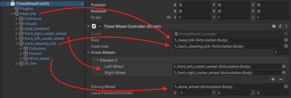
- Root - this should be the first ArticulationBody in your chain; the topmost parent.
- Steer Axle - this should be the ArticulationBody component that is responsible for turning the wheel when steering the vehicle.
- Front Wheels - these can be any amount of caster wheels added in pairs. They will not be participating in driving or steering the vehicle, but will only help support the vehicle. Drag the Game Objects in that have the ArticulationBodies with the revolute joints which will be rotating freely.
- Driving wheel - this is the actual wheel that will be driving the vehicle. Drag the Game Object into this field that has the revolute joint ArticulationBody component responsible for rotating the wheel along the ground.
- Local Forward Direction - a direction vector that specifies which way the vehicle is facing. Meaning driving forward will move the vehicle in that direction. The direction is local to the root Articulation Body of the chain! This is used to determine the if the vehicle is front steered or rear steered.
Keyboard Adapter
If you chose to use the Keyboard Adapter, adjust the max steering angle, the steering velocity (this is the velocity that the wheels will reach when rotating to the desired rotation), max linear velocity, linear acceleration, and jerk. Linear speeds are measured in meters per second, while steering velocity is in degrees per second.
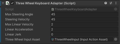
- Max Steering Angle - the maximum angle that the steering wheel will be trying to reach, measured in degrees.
- Steering velocity - the speed at which the steering wheel will try to rotate at, measured in degrees per second.
- Max Linear Velocity - the maximum linear velocity that the vehicle will try to move at, measured in meters per second. A value of 0 is interpreted as an instant change.
- Linear Acceleration - the rate of change of velocity, or how fast will the robot accelerate, measured in meters per second squared. A value of 0 is interpreted as an instant change.
- Linear Jerk - the rate of change of acceleration, measured in meters per second cubed. A value of 0 is interpreted as an instant change.
- Three Wheel Input Asset - the InputActionAsset which will be used to capture input from the keyboard. If not set already, set it to the "ThreeWheelInput" asset from the package three wheel adapters folder.
Connector adapter
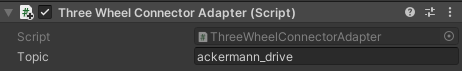
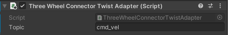
If you are using the Connector adapter, you can set the topic, which the connection will try to use to subscribe to the message.
Authoring
Let's move onto the Three Wheel Authoring script. It is an optional script that makes it easier to set up all the relevant ArticulationBody parameters of your robot.
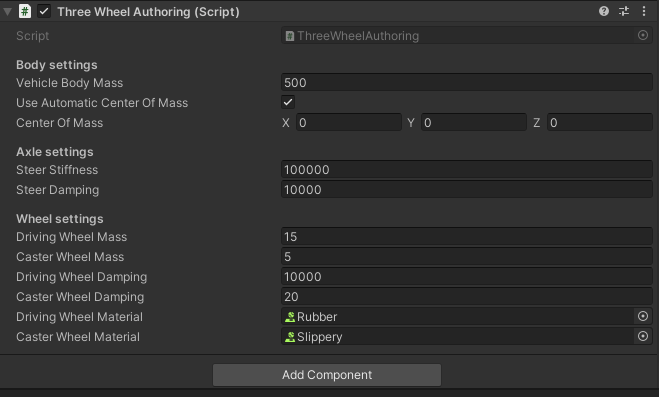
- Vehicle Body Mass. The mass of the root of the body measured in kilograms.
- Automatic Center Of Mass and Center Of Mass. Change the center of mass to fit your robot or leave it as Automatic. When set to use Automatic, the Center of Mass will be calculated based on the Articulation Bodies and their colliders.
- Steer Stiffness and Damping. Stiffness is the strength of the spring that tries to reach the target position setpoint on the steering axle, while damping controls the velocity-damping effect of the spring. Damping also controls how fast the ArticulationDrive tries to reach the target velocity setpoint. These values are set for the ArticulationDrives of each body and not for the ArticulationBodies themselves! For a more in-depth explanation on how the ArticulationDrive reaches its targets, read more in the ArticulationBody Manual page
- Driving and caster wheel masses. The higher the driving wheel mass, the better results it will have when trying to reach the given target velocity. In other words, if you imported your vehicle model using URDF-Composer, such that you're using the wheel masses specified by your URDF, and you're finding that the vehicle isn't reaching its target velocity, try increasing the wheel masses by 2x or 3x (not 50x or 100x). The small wheel mass has less of an impact on the simulation.
- Driving wheel Damping. The strength of the spring that tries to reach the given target-velocity setpoint. This will set the Damping term on both driving wheel ArticulationDrives. This value is set for the ArticulationDrive of each of the bodies and not for the ArticulationBodies themselves! For a more in-depth explanation on how the ArticulationDrive reaches its targets, read more in the ArticulationBody Manual page
- Small wheel Damping. It's good to use some non-zero value to reduce caster wheel oscillation during the simulation. This property is NOT set for the Damping values of the ArticulationBody itself, but for the ArticulationDrive within the body component.
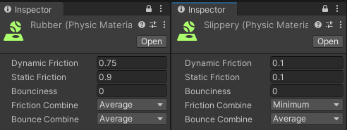
- Wheel Materials. These are Unity Physic Material objects, which can be created by right-clicking on the Project window -> Create -> Physic Material. The driving wheels should have a higher-friction material and the caster wheels should have a very slippery one.
Congratulations! You should now have a three-wheel-drive robot that is controlled either by keyboard or by sending ROS messages!