Warning
Warning: Unity Simulation is deprecated as of December 2023, and is no longer available.
Set up a differential-drive controller
Now that our differential-drive vehicle model is in the scene, we want to add the corresponding controller.
What is the differential drive method?
This two-wheel controller can operate any vehicle that is "differential-driven." Such a vehicle consists of two drive wheels mounted on a common axis, where each wheel can independently rotate either forward or backward. Many robots use this kinematic configuration because the robots can rotate in place, making planning through tight spaces easier.

Based on this concept, we only need to know the desired linear and angular velocities, and we can calculate the required wheel velocities from that.
Interface
ROS Message
geometry_msgs/Vector3 linear
  float64 x
  float64 y
  float64 z
geometry_msgs/Vector3 angular
  float64 x
  float64 y
  float64 z
C# Interface
using System;
using UnityEngine;

namespace Unity.Simulation.VehicleControllers
{
    [Serializable]
    public struct DifferentialDriveControlMessage
    {
        public Vector3 linear;  // desired forward velocity (m/s). Only x of the ROS vector is used (z of the Unity vector)
        public Vector3 angular; // desired angular velocity (rad/s). Only z of the ROS vector is used (y of the Unity vector)

        public override string ToString()
        {
            return $"(Linear.x: {linear.x}, Linear.y: {linear.y}, Linear.z: {linear.z}, Angular.x: {angular.x}, Angular.y: {angular.y}, Angular.z: {angular.z})";
        }
    }
}
Warning
Units of measurement
Unity uses meters as the default measurement unit, so linear speed is measured in meters per second. Angular speed is measured in radians per second. Though keep in mind that the pre-made keyboard adapter will be accepting degrees per second as input as this is easier to conceptualize!
Warning
Coordinate system chirality (handedness)
Unity uses a left-handed coordinate system while ROS uses a right-handed one. In Unity, the X axis points right, Y up, and Z forward. In ROS, the X axis points forward, Y is left, and Z is up. You can read more about it here.
The drive interface accepts linear and angular velocities.
linear.x - This is the target velocity in the x axis, which equates to the forward or backward motion. Positive means going forwards, while negative means going backwards. The calculated target velocities will then be sent directly do the ArticulationDrives of the ArticulationBodies that are defined in the Left_Wheel and Right_wheel fields for each pair.
angular.z - This is the target velocity around the z axis. A positive value means rotation in the clockwise direction when viewed from the top of the robot downwards. A negative value will rotate the robot counter-clockwise. Same as with linear velocity, the calculated targets are sent to the ArticulationBody drives that are defined in the left and right wheel fields for each pair.
All the other axes (linear.y, linear.z, angular.x, angular.y) are ignored, because movement in those axes would be impossible
The maximum limits for each axis of movement can be set by using the Authoring script or simply by going to each ArticulationBody and changing the upper and lower limits on the ArticulationDrive.
Now let's add some C# components!
Add the following components to the root GameObject of your robot:
- DifferentialDriveController
- DifferentialDriveKeyboardAdapter OR DifferentialDriveROSAdapter - Choose an adapter according to how you intend to control the robot.
- DifferentialAuthoring
One thing to keep in mind is that your wheels should be using Sphere Colliders, even though their visual shape might be a cylinder. This will improve results of the physics simulation and the ability of the robot to reach target setpoints.
Configurable parameters
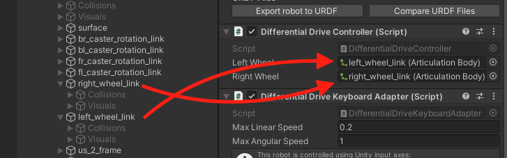
Controller
Drag the corresponding wheel links to the fields on the controller
Keyboard Adapter
If you are using the keyboard adapter, choose appropriate max speeds for your project. Linear speed is measured in meters per second, while angular speed is in radians per second.
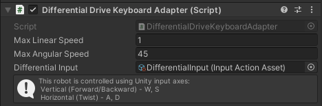
- Max Linear Speed - this is the maximum linear speed that the robot will try to reach, measured in meters per second.
- Max Angular Speed - this is the maximum angular speed that the robot will try to reach, measured in degrees per second.
- Differential Input Asset - the InputActionAsset which will be used to capture input from the keyboard. If not set already, set it to the "DifferentialInput" asset from the package Differential adapters folder.
Connector Adapter
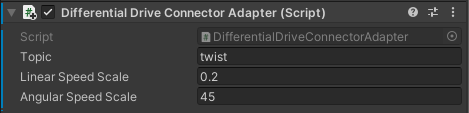
If you are using the Connector adapter, you can set the topic, which the connection will try to use to subscribe to the message. Also, you can scale the incoming input for Linear and Angular speeds using the Speed Scale properties.
Authoring Script
Let's take a look at the Authoring script. This part is purely optional and is only meant to help you set the ArticulationBody values on provided bodies.
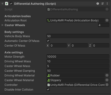
- Articulation Root. This should be the first ArticulationBody component in your chain—the root of the whole robot—not necessarily the topmost parent GameObject. For example, if you imported your vehicle model using URDF-Composer, then the first ArticulationBody component will not be at the topmost GameObject.
- Caster wheels. Here you can define all of the wheels that support the robot.
- Vehicle Body Mass. The mass of the root of the body measured in kilograms.
- Automatic Center Of Mass and Center Of Mass. Change the center of mass to fit your robot or leave it as Automatic. When set to use Automatic, the Center of Mass will be calculated based on the Articulation Bodies and their colliders.
- Motor Strength. The strength of the spring that tries to reach the given target-velocity setpoint. This will set the Damping term on both driving wheel ArticulationDrives. This property is NOT set for the Damping values of the ArticulationBody itself. Those should be configured manually or left to the default values. For a more in-depth explanation on how the ArticulationDrive reaches its target, read more in the ArticulationBody Manual page
- Driving and Caster Wheel Masses. The higher the driving wheel mass, the better results it will have when trying to reach the given target velocity. In other words, if you imported your vehicle model using URDF-Importer, such that you're using the wheel masses specified by your URDF, and you're finding that the vehicle isn't reaching its target velocity, try increasing the wheel masses by 2x or 3x (not 50x or 100x). The caster wheel mass has less of an impact on the simulation.
- Caster Wheel Damping. This Damping value is set for each ArticulationDrive of the Caster wheels that are defined above. This property is NOT set for the Damping values of the ArticulationBody itself. Those should be configured manually or left to the default values. It's good to use some non-zero value to reduce caster wheel oscillation during the simulation.
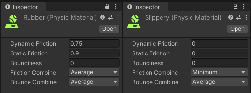
- Wheel Materials. These are Unity Physic Material objects, which can be created by right-clicking on the Project window -> Create -> Physic Material. The driving wheels should have a higher-friction material and the caster wheels should have a very slippery one.
- Disable Inter Collision - Whether to disable colliders of the robot colliding with each other. This is useful when the different colliders of the robot are overlapping each other and causing simulation instabilities. For the UnityAMR this should be set to true
Odometry Publisher
There is one more component that you will find in the differential drive stack and that is the odometry publisher. The component will track the movements of the wheels and output a predicted position and velocity of the robot in the reference map of where the robot was when the application started (Editor entered play mode).
On start, the publisher will attempt to connect to ROS and will keep publishing the Odom nav message at the specified rate.
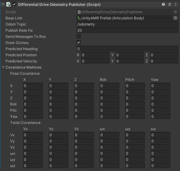
- Base Link - This is a reference to the base link of the robot.
- Odom Topic - The topic that this publisher should use when publishing the message.
- Publish Rate Hz - The rate at which it should publish messages.
- Send Messages To Ros - Whether the component should publish messages or not.
- Predicted Heading - This is a predicted heading, or rotation along Y axis, where 0 is the initial starting point when the simulation was started. This property is measured in radians.
- Predicted Position - The predicted position of the robot, where (0, 0, 0) is the initial starting point when the simulation was started. This property is measured in meters.
- Predicted Velocity - The predicted velocity of the robot, measured by the rate of change of the predicted position. This property is measured in meters per second.
- Draw Gizmos - Whether to draw the underlying red gizmo or not.
- Covariance Matrices - The position and velocity covariance matrices, which are calculated using the difference between what the predicted position is and what the ground simulation truth is to generate each member of the matrix. Keep in mind that most fields are 0, since no movement is possible on those axes.
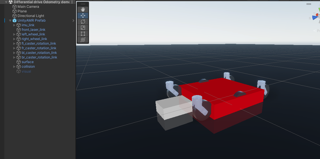
The red gizmo under the robot visualizes the predicted position and angle of the robot. It is basically where the odometry map "thinks" the robot is. Factors like wheel slip or uneven ground can greatly reduce the accuracy of this prediction. For this reason the 4 wheel robot does not do well with the odometry publisher, because the 4 wheel differential drive has wheel slip inherent to its design.
Congratulations! By now you should already be able to control your robot by using the keyboard or by inputting some ROS commands!