Warning
Warning: Unity Simulation is deprecated as of December 2023, and is no longer available.
Vehicle Controller sample scenes
Along with the controllers, we have made some sample demo scenes that show off how each robot could be set up. In this page we'll go over each sample and familiarize ourselves with what each scene is demonstrating.
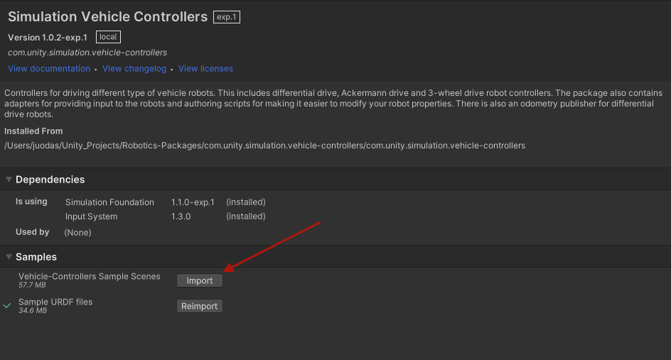
To import these samples, navigate to the Unity Package Manager window and select the Vehicle Controllers package. There you should see a tab called "Samples". Click the "Import" button next to the Sample Demo scenes item and it will extract the unity package into your project.
IMPORTANT: The sample materials were built using the High Definition Render Pipeline (HDRP) package and therefore should be opened in projects that were set up with HDRP, otherwise the materials will be rendered as pink.
Ackermann Drive Scenes
Ackermann Forklift Demo Scene
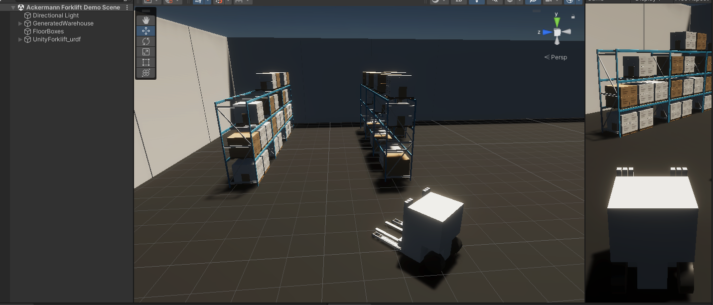
This is a scene demonstrating how the Ackermann drive could be used to control an autonomous forklift with back powered and steered wheels.
In this scene you can input controls using the:
- WASD keys to move the robot
- Arrow keys to control the carriage/fork vertically and laterally
- C and V keys to control the fork longitudinally
- R and F keys to control the tilt of the fork
You can drive around and try to pick up one of the pallets with the fork.
Various Ackermann Setups Demo Scene

This is a scene demonstrating the various possible configurations of the Ackermann drive. For example you can have a classic automobile with front powered wheels and front steered wheels like the Honda Accord or the back powered front steered wheels like the BMW 3 series. Or a Firetruck that has 4 axles with a total of 8 wheels, powered and steered from the front.
The concentric circles show the trajectory of each wheel. The direction arrows show the Local Forward and Local Up Directions set in the controller component.
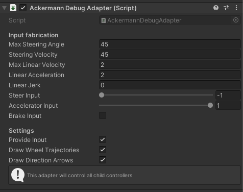
All of the vehicles are controlled using a convenience component called the Ackermann Debug Adapter. It sets some values for all of the children vehicles and draws the trajectory and direction gizmos.
Conveyor Belt Scene
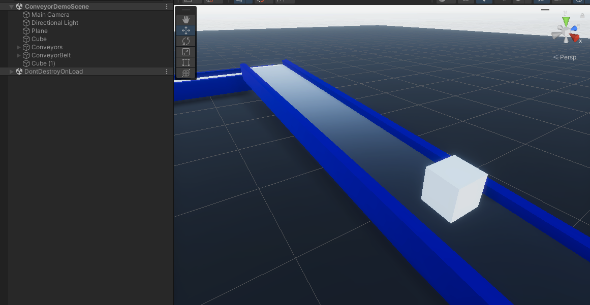
In this scene we demonstrate that you can build a simple conveyor belt for your simulation using the Contact Modification API.
There are no controls, but you can add more boxes, spheres or any rigidbodies to see how the simulation is affected.
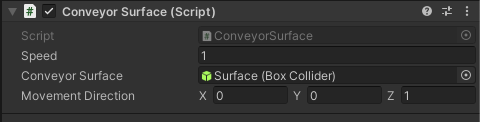
The Conveyor Surface component adds a listener for modifying contacts and enables the appropriate flag for the collider. When the Cube collides with the belt, it tells the solver to move the body alongside the given direction.
Three Wheel Scene
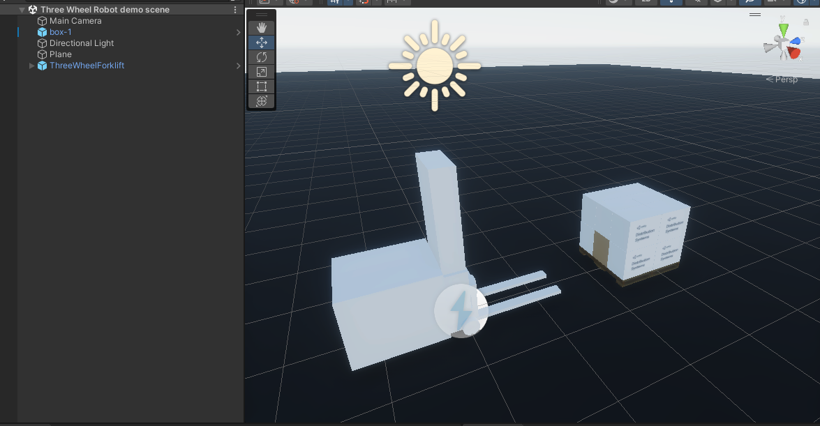
This is a scene demonstrating how the Three wheel drive could be used to control an autonomous forklift with a single back powered and steering wheel.
In this scene you can input controls using the:
- WASD keys to move the robot
- UP/DOWN Arrow keys to control the fork vertically
Differential Drive Scenes
Differential drive demo scene

This is a simple scene, set up using the UnityAMR as a base, wth all of the components attached to the UnityAMR Prefab gameObject.
In this scene you can input driving directions using the WASD keyboard keys and observe the robot driving around.
4 Wheel Differential Drive demo scene

This scene is meant to demonstrate that you can use the differential drive with more than one pair of wheels. Keep in mind that with more than one pair, the wheels will have to start slipping, when the robot is turning. This may affect things like odometry output.
In this scene, much like the previous simple differential demo, you can input driving directions using the WASD keyboard keys and observe the robot moving around using two pairs of driving wheels.
Differential drive Odometry demo scene

This scene shows off the Differential Drive odometry publisher component. The component will track the movements of the wheels and output a predicted position and velocity of the robot in the reference map of where the robot was when the application started (Editor entered play mode).
When you enter play mode, the attached Odometry Square Test component will drive the robot in a square, following 4 commands of Drive forward at 1 m/s for 4 seconds and Turn 90 degrees in 4 seconds.
You can remove the Odometry Square Test component and add a Differential Drive Keyboard Adapter to manipulate the robot manually and see how the predicted model keeps track of its position.
On start, the publisher will attempt to connect to ROS and will keep publishing the Odom nav message at the specified rate.
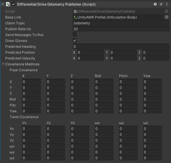
- Base Link - This is a reference to the base link of the robot.
- Odom Topic - The topic that this publisher should use when publishing the message.
- Publish Rate Hz - The rate at which it should publish messages.
- Send Messages To Ros - Whether the component should publish messages or not.
- Predicted Heading - This is a predicted heading, or rotation along Y axis, where 0 is the initial starting point when the simulation was started. This property is measured in radians.
- Predicted Position - The predicted position of the robot, where (0, 0, 0) is the initial starting point when the simulation was started. This property is measured in meters.
- Predicted Velocity - The predicted velocity of the robot, measured by the rate of change of the predicted position. This property is measured in meters per second.
- Draw Gizmos - Whether to draw the underlying red gizmo or not.
- Covariance Matrices - The position and velocity covariance matrices, which are calculated using the difference between what the predicted position is and what the ground simulation truth is to generate each member of the matrix. Keep in mind that most fields are 0, since no movement is possible on those axes.
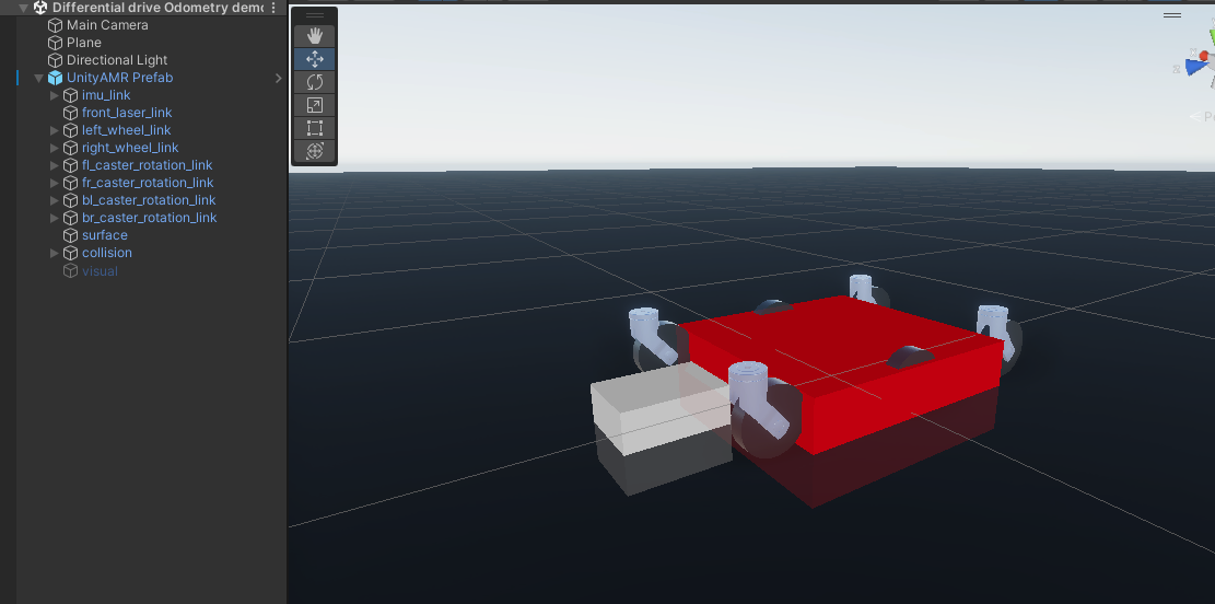
The red gizmo under the robot visualizes the predicted position and angle of the robot. It is basically where the odometry map "thinks" the robot is. Factors like wheel slip or uneven ground can greatly reduce the accuracy of this prediction. For this reason the 4 wheel robot does not do well with the odometry publisher, because the 4 wheel differential drive has wheel slip inherent to its design.