Configuration
Physics
The following settings are some of the most important ones for the vehicle behavior/handling:
- Vehicle physics update rate
- High speed vehicles should use a higher physics update rate to maintain proper vehicle physics quality.
- Either increase the fixed step system group update rate, or increase
VehicleAuthoring > Substep Count.
Rigidbody > Center of Mass(can be adjusted after un-ticking theRigidbody > Automatic Center of Massoption)- Too high center of mass can make the vehicle prone to tipping over or rolling.
- Too low center of mass will make the vehicle lean the wrong way in corners.
Rigidbody > Inertia Tensor(can be adjusted after un-ticking theRigidbody > Automatic Tensoroption)- Too low values will result in a vehicle that rotates easily, making it very sensitive to steering input or bumps, with the too high values having the opposite effect.
Vehicle
Vehicle Authoring
VehicleAuthoring is the base of the vehicle and contains only the settings relating to the base vehicle physics.
AxlePairedWheelsrepresent vehicle axles with two wheels. If there is a single wheel on the axle (e.g. a motorcycle) the wheel should be left out from this list. Only the left-right pairs of wheels should be added, in that order. This list is used to calculate Ackerman steering and Anti-roll bar values.Dimensionsare important as they determine the scale of some of the physics calculations. They are also used for aerodynamic calculations.
Vehicle Control Authoring
VehicleControlAuthoring adds control-related functionality to the vehicle.
- For vehicles with varying driven wheel radii (those wheels that have
MotorTorqueCoefficient > 0),EngineAngularVelocityCalculationshould be set toMinimumfor correct engine angular velocity results. Setting it toMaximumorAveragein this case will under-report the angular velocity. - In case of a combination of high
EngineMaxTorqueand highEngineBrakingIntensityvalues, the wheels may lock up when the there is no throttle input, as the engine braking torque might result in higher torque than the friction can handle. TransmissionForwardGearRatiosandTransmissionReverseGearRatiosshould always be in a descending order. Higher gear ratio means a lower numbered gear.
Wheel
Wheel Authoring
WheelAuthoring contains settings relating to the base wheel and suspension functionality.
Suspension
Vehicle suspension consists of a spring and a damper. The spring provides the force required to keep the suspension extended, while the damper opposes changes in spring length to dampen the oscillation.
SuspensionSpringRateshould keep the vehicle at ~30% spring compression when at rest on a flat surface. Too low values will result in suspension that has little available ssuspension travel in compression, while too high values will result in the suspension easily reaching the fully extended state and lifting off the ground.SuspensionDampingRatedoes not affect the ride height, only the reluctance for the spring length to change. Too low values will result in a suspension that is bouncy, while too high values will make the suspension over-damped.AntiRollBarStiffnessreduces the vehicle roll in corners. After the vehicleRigidbody > CenterOfMassis properly configured,AntiRollBarStiffnesscan be used to further reduce any unwanted roll. Overly stiff anti-roll bar reduces the effectiveness of the suspension. Note that thisAntiRollBarStiffnesshas effect only if the wheel is present in theVehicleAuthoring > AxlePairedWheels.RigidbodyCenterOfMassshould be correctly set before increasing theAntiRollBarStiffness. A too highCenterOfMasswill make the vehicle want to roll over, and if it is over-corrected with theAntiRollBarStiffnessthe vehicle will tend to roll suddenly as one of the wheels lifts of the ground.
Friction
Tire friction is adjusted through the friction curve, represented with three points:
[0,0]- The graph always starts at zero, since with no tire slip there is no friction force.frictionCurveMaximum- Represents the peak of the curve. This is the slip at which point there is the most grip available.frictionCurveMinimum- Represents the local minimum of the curve, after thefrictionCurveMaximum. Any amount of slip after thefrictionCurveMaximumwill reduce the grip available.
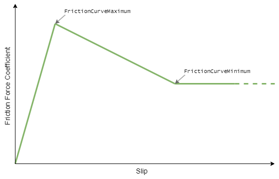
The x axis in both frictionCurveMaximum and frictionCurveMinimum represents the tire slip value, and the y axis represents the force coefficient.
Tips:
- The
y(force coefficient) value of the friction curve can be reduced to simulate driving on slippery surfaces. - The
x(slip) value of the friction curve can be reduced to simulate driving on soft surfaces or on deflated tires. - Having too stiff friction for the given simulation frequency (too high
frictionCurveMaximum.yor too lowfrictionCurveMaximum.x) can result in vehicle easily losing control, or in extreme cases it can cause jitter.
Casting
The ground detection is based on casting a cylinder-shaped convex mesh collider along the suspension travel. The number of sides of this cylinder that can be adjusted through the WheelColliderSideCount. Use the lowest WheelColliderSideCount that is adequate for the use case as this setting has a high impact on performance.
Wheel Protector Colliders
In order to properly handle suspension bottoming-out or wheel side-hit scenarios, Wheel Authoring > Add Wheel Protector Collider should be enabled. This will modify the collider of the vehicle rigidbody to include child wheel colliders (same colliders that are used for casting) where the wheel suspension origins are, making sure physics impacts to those wheels are properly transferred to the vehicle rigidbody. Without these, if the wheel suspensions cannot support the down force of the vehicle body, the wheels would start going through the ground.
Controllable Wheel Authoring
Adds control-related functionality to the wheel. Add this Component if the wheel needs to accelerate, brake or steer.
All the values on the ControllableWheelAuthoring are coefficients relating to the values that the VehicleControl calculates. For example, the VehicleControl calculates that the user input is requesting 20,000N of brake torque, so if the BrakeTorqueCoefficient is set to 0.5, the value that particular wheel will receive is 10,000N.
With the MotorTorqueCoefficient the situation is a bit different as it acts as a weight when distributing the torque between the individual wheels.
Tips:
- Rear wheels on most vehicles should have lower
BrakeTorqueCoefficientdue to the weight transfer towards the front under braking. - The
MaxSteerAngleDegreesdetermines the maximum steer angle of the outside wheel whenAckermanCoefficient > 0. The actual steer angle of the inside wheel will be higher to accomodate for the turning circle. This will be the opposite in the case ofAckermannCoefficient < 0.