SensorSDK - Architecture
Prerequisites
This documentation is for readers who are already familiar with SystemGraph. See the SystemGraph architecture documentation for more information.
Simulation sample rate
Simulation time step
The sample rate of sensors is an important factor in sensor emulation. Lidars, for example, are continuously sampling the environment, while cameras take a snapshot at a specific moment in time. This is a challenge, as it requires the simulation to update at the sampling rate of the lidar. Lidars use high sampling rates (millions of samples per second), and it's not practical to simulate this sample rate. Instead, lidars take many samples of the same simulation state. You can configure the simulation time step through the Global System Graph component.
Discontinuity in the lidar sweep
The simulation time step also defines how much of the circular sweep the lidar uses during the same simulation state. This might cause some correlation artifacts between different sampled portions, since they might have been taken in a different position.
SensorSDK uses Trajectory components to determine the photosensor position and orientation precisely in-between two simulation states. However, this doesn't apply to the objects being scanned by the lidar. The position of a fast-moving object will be the same for all lidar samples evaluated for a given simulation state.
Camera vs sensor output
Glitches or issues with the point cloud position might arise if the camera updates faster than the point cloud position. Some lidars update the point cloud at the end of the 360° sweep, which causes the "frame rate" of the point cloud to be slower than the camera. This causes the point cloud to appear fragmented due to the lidar sweep rate (rotation speed in hertz).
Simulation update
The simulation update executes when Unity calls FixedUpdate() and Update() on the client code. The SystemGraph node update OnTick() is called on one of these events.
The SystemGraph node update can execute at higher frequencies than Unity's thanks to the scheduler. The scheduler is able to execute OnTick() several times during an Update() or FixedUpdate(), ensuring that the desired frequency is met in aggregate.
Synchronization
To make sure the GPU sampling works, a graph node must send a sampling request to the photosensor or photosensor array during the simulation update. It's recommended to control this from a single node, or a sensor controller. The designer must know that the scene is static while the photosensor is processing sampling requests, such as GPU Sampling. The sampling shader interpolates the position and orientation of the photosensor, but not of other objects in the scene.
Note
For better accuracy, lower the simulation time step to a comfortable level. Time step should be low enough such that fast moving objects don't change drastically between frames.
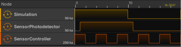
The diagram below explains how the simulation, sensor controller and the photosensor synchronize together.
Note
The Scheduler nodes displayed here are for demonstration purposes, and aren't available in SensorSDK.
The simulation rendering and the sensor photosensor are coupled together. The photosensor takes its measurements at simulation render time, after executing the Update() callback on all MonoBehaviour of the scene. In other words, it takes its measurements when the simulation renders. In the example above, an offset was added to the SensorPhotodetector to display the order of these events.
To make sure the sensor captures fast moving objects in the simulation, you must set the simulation step to at least 4 to 10 times the period of the fastest moving object. In other words, it must be fast enough to capture maximal displacement for non-periodic movement, depending on the simulation capture requirements.
To ensure the photosensor gets exactly one sampling request for each simulation time step, select the Use ClockSource Frequency scheduler option for the controller node, and use Update as clock source for the scheduler.
Simulation sampling
SensorSDK currently has support for diffuse (lambertian) materials in the near infrared spectra (~700-1500nm). No other sources of infrared light are taken into account in the current lighting equations, as SensorSDK only emulates direct lighting from the lidar laser itself. For more information, see the Beam divergence page.
To compute the intensity reflected on the surface from the light source, SensorSDK uses the same lighting model as physically based rendered games. The measurement units have changed to match lidar wavelengths.
SensorSDK has the following lighting differences:
- The intensity unit changed from lumens to W/m².
- Support to override the albedo with the right reflectance, depending on the laser light wavelength.
For more information on the light equations, refer to physically based rendering on the web.
Rendering Pipeline
SensorSDK uses a modified Graphics rendering pipeline to be able to provide laser beam characteristics and material flexibility to handle different light wavelength and reflectance for the simulation.
This section complements the sensor developer guide and provides a detailed explanation of the rendering pipeline.
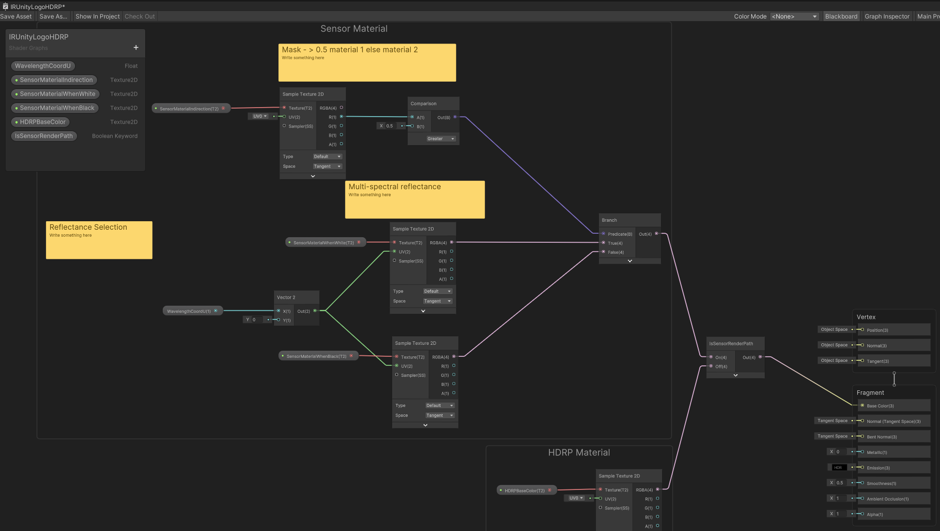
Material
SensorSDK materials must handle special parameters to enable proper simulation of laser beam. The example below displays the parameter structure in Shader Graph.
Light Beam
The light information of the rendering pipeline supplements the rendering with light beam characteristics, such as:
- Wavelength
- Divergence
- Intensity
- Power
- Beam diameter