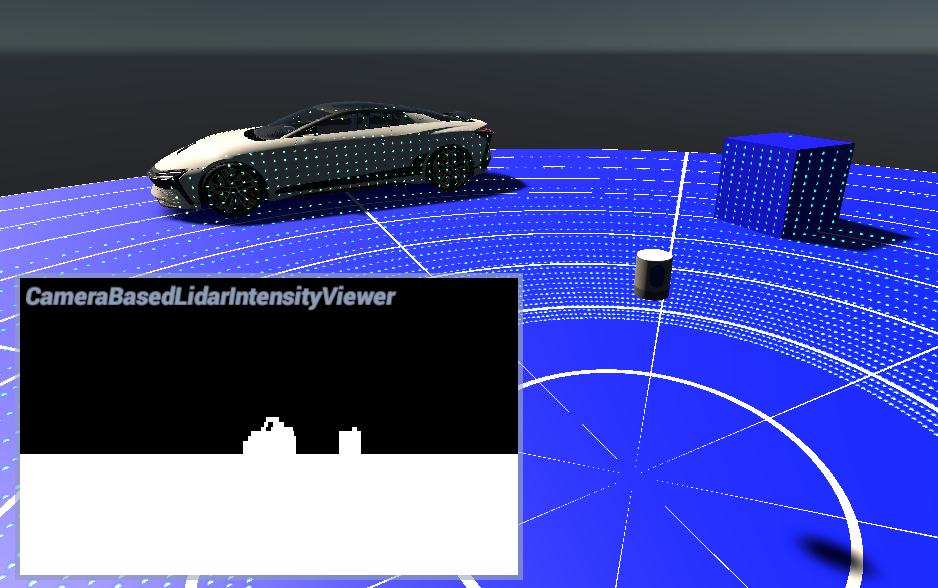
Camera-Based Lidar
The main purpose of this prefab is to let the user define their own specifications for a standard mechanical 3D lidar. The term mechanical here means that it's a laser rotated by a dc motor. A 3D lidar is a lidar that scans on several planes with multiple beams.

Implementation details
This lidar samples the scene using a Unity camera with deferred rendering. The initial position (0 degree) of the lidar is toward its positive Z axis. The rays orientation is interpolated using the previous rotation and the current rotation. This interpolation is driven by the sampling rate. The heuristic in the shader assumes the photosensor will rotate on itself.
There is also the possibility to sample all beams at the same time (all at the same orientation) or interpolate the rotation between each sample (see IsCellsSync input below).
When the scene is sampled, the photosensor rotates on itself but everything else is static (including the photosensor position). To avoid having too many samples sampling a static scene, it's important to keep the simulation update time (dt) as small as possible.
This implementation uses a Unity camera instead of path tracing, which means it does not require DXR, unlike other lidar implementations.
Assumptions
The current implementation relies on a few assumptions that could be eventually relaxed in future versions:
- Beams sampling offsets are roughly oriented along the positive Z axis.
- This prevents using most scan patterns (e.g. MEMS lidar).
- Photosensor angular speed is constant.
- Photosensor has no roll rotation.
Limitations
Using a Unity camera instead of path tracing to simulate a lidar lowers hardware requirements, as DXR is not necessary anymore. However, it comes with some limitations.
All beams must intersect at the camera pinhole. A lidar beam must follow a camera ray, and by definition of a perspective camera, all rays converge to the pinhole. This have the following consequences:
- Sampling offset positions must be (0,0,0). The translation between laser diodes in multi-beam lidars is ignored.
- Lidar position cannot be interpolated in-between Unity updates. If the lidar is moving in the scene and multiple sampling requests are resolved in the same Unity update, they will all use the final lidar position, introducing translational error.
Advanced optical effects like refraction and multiple reflections cannot be simulated.
Lidar segmentation using the Perception package is not supported.
Trade-offs
Lidars usually have constant angular difference between consecutive beams, while cameras have constant translational difference between consecutive pixels. Thus, some approximation must be made, leading to slight depth inaccuracies compared to a ray tracing implementation.
The MaxApproxErrorDeg property can be used to configure the maximum approximation angular error, that is, the maximum angle between the desired lidar beam and the closest camera ray going through a pixel center.
This is used to compute the texture size used by the camera. The smaller the requested maximum error, the more graphic memory is required.
To be implemented
- Physically-based intensity measures, taking sensor area and material into account (currently using luminance)
- Sensitivity, the minimum detectable amount of light
- Wavelength specification
- Relative depth error
- Beam divergence
- Smart bilinear texture interpolation for higher accuracy (currently nearest neighbor)
Inputs
| Input | Description |
|---|---|
| SamplingRate | This defines the number of samples per second the photosensor must take. |
| RotationSpeedHz | The photosensor rotation speed represents the number of turns per second the object will rotate on itself around the Y axis. |
| MinRange | Sets the minimum range registered by the device |
| MaxRange | Sets the maximum range registered by the device. Every sample outside the max range will have a distance of 0 meters. |
| RelativeDepthError | The curve representing the relative depth error as a normal distribution. 0 means no relative error. |
| SpeedVariation | The standard deviation of the motor speed. |
| TurnCW | When selected, indicates the motor turns clockwise. |
| TimeConstant | The time required to reach 63% of the max RPM for the motor. |
Outputs
| Output | Description |
|---|---|
| PointCloud | A render texture with the (x, y, z) position for each pixel. The lidar frame is spread from left to right in the texture. To know the point count, one can look at the count value in this structure. |
| Intensity | A corresponding render texture with the perceived intensity for each pixel. |
| OutTranscode | Provides a context for executing sampling custom passes, which then passes through the GPU processing pipeline. |