Use SystemGraph to create a new 2D sensor
Overview
This guide describes the creation and setup of a 2D sensor from a new project in the Unity Editor.
Set up the system graph
Create a new system graph
To create a new sensor graph:
In the Editor, go to Assets > Create > System > System Graph
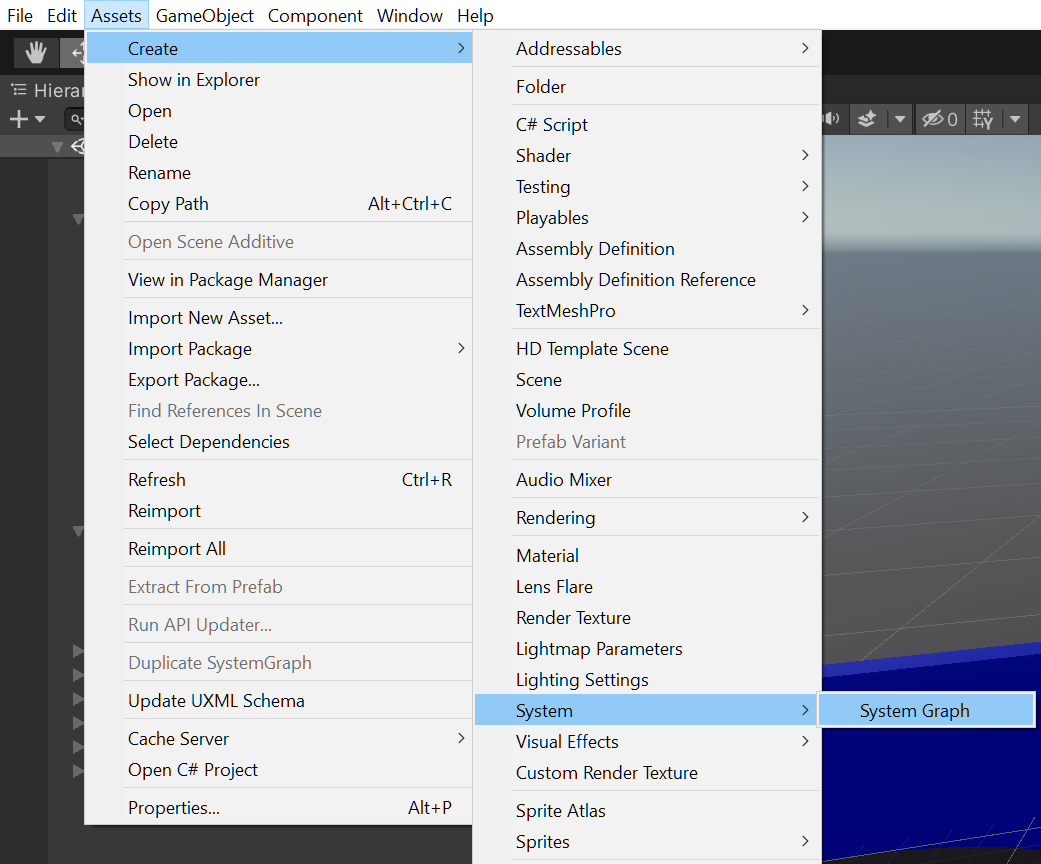
Name the system graph 2DLidarTest.
- The system graph window should open automatically. To open manually, go to the Project tab and double-click the system graph.
Create the required nodes
In an empty area on the system graph, right-click and select Create Node.
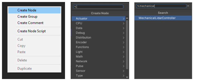
A list of node types displays in the drop-down menu. You can also use the search box to find matching terms.
Use Create Node to make the following nodes for your project:
- MechanicalLidarController node.
- Photosensor node.
- DC Motor node.
- PhotosensorToPointCloud node.
- Point cloud viewer node.
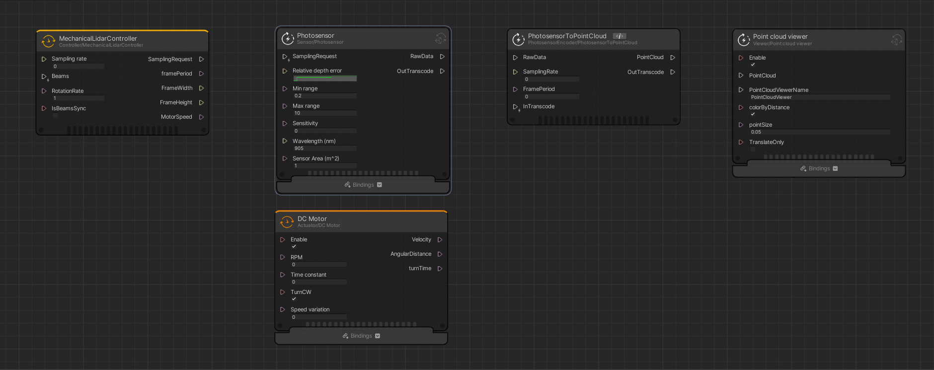
After creating the nodes, arrange them in the order listed above. For best results, place the DC Motor node under the Photosensor node.
Create the properties
Under the Properties tab, select the add button ( + ) and then select UInt.
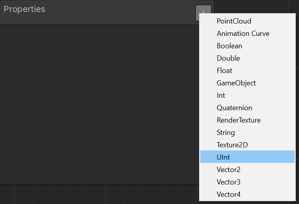
Enter the name SamplingRate.
Expand the SamplingRate attributes and enter a default value of
2500.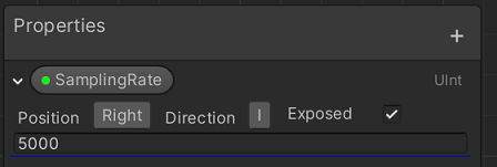
Use the add button ( + ) to create another property, and then select Float .
- Rename the property to RotationRate.
- Expand the RotationRate attributes and enter a default value of
5.
Connect the properties
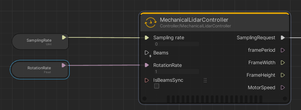
- Drag each property from the Properties window to the left side of the MechanicalLidarController node.
- Connect the SamplingRate property to the Sampling rate port on the node.
Connect the RotationRate property to the RotationRate port on the node.
Connect the nodes in the system graph
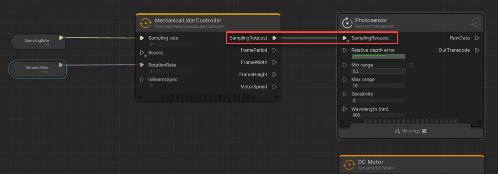
On the Photosensor node, connect the SamplingRequest ports.
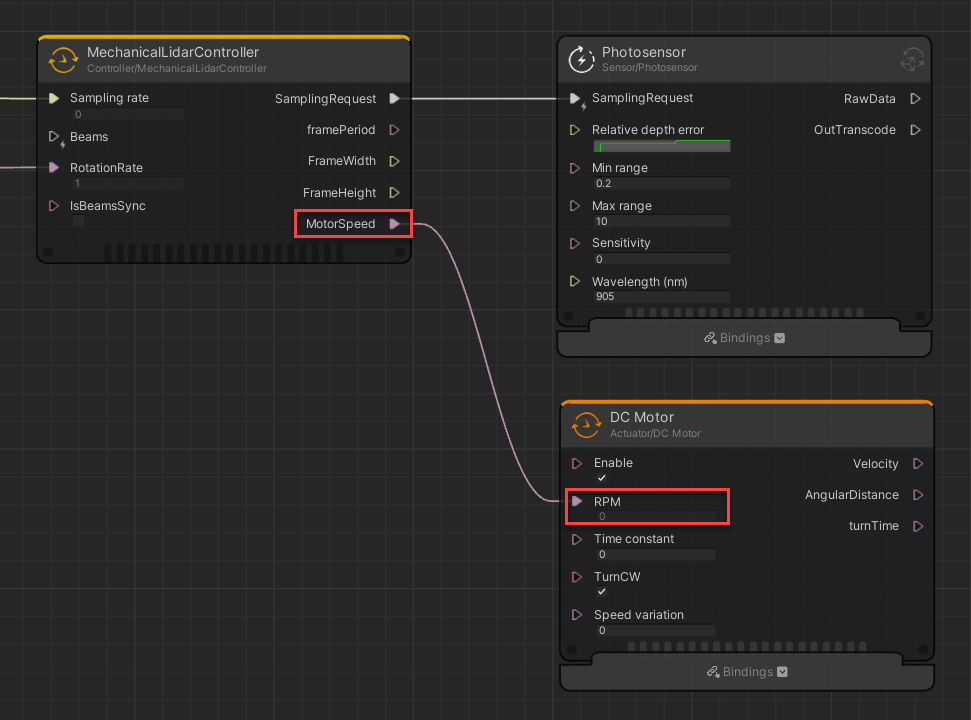
Connect the MotorSpeed port on the MechanicalLidarController node to the RPM port on the DC Motor node.
On the PhotosensorToPointCloud node, connect the ports from the following nodes:
- Photosensor node:
- RawData to RawData
- OutTranscode to InTranscode
- DC Motor node:
- turnTime to FramePeriod
- SamplingRate property:
- SamplingRate to SamplingRate
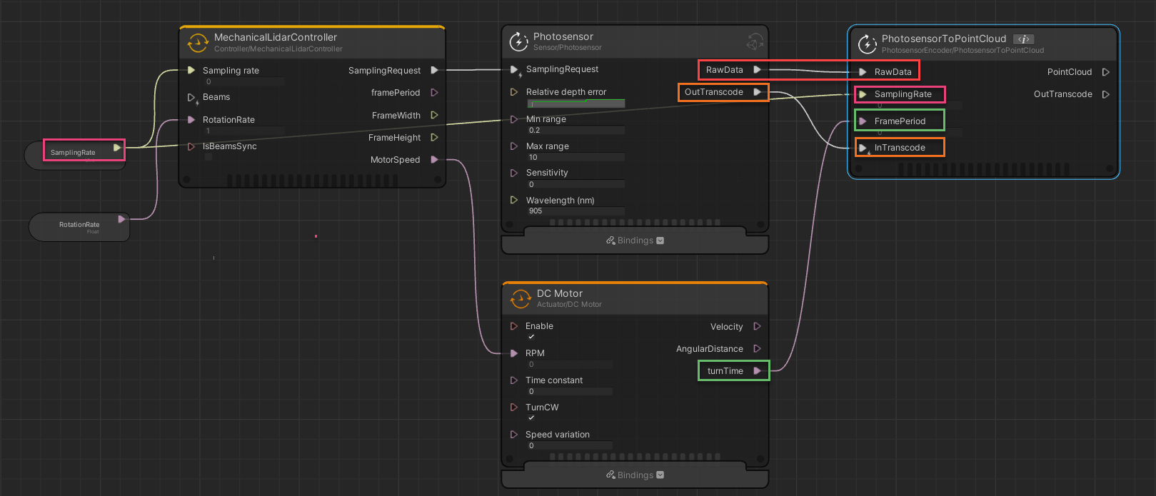
Refer to the node connections image for more detail.
- Photosensor node:
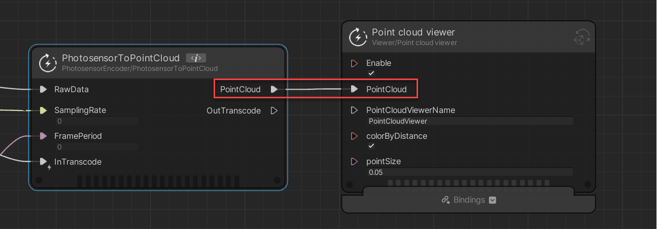
Connect the PointCloud ports from the PhotosensorToPointCloud node to the Point cloud viewer node.
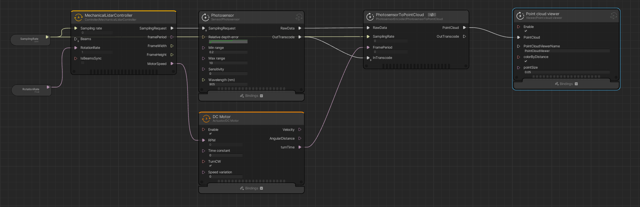
After connecting all nodes, refer to the graph node diagram to make sure all corrections are correct.
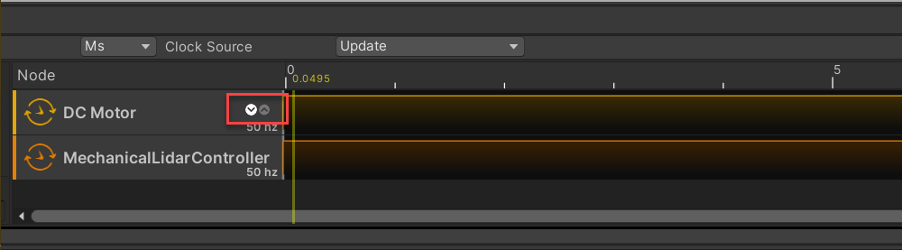
Configure the Scheduler
- In the Scheduler panel, double-click the DC Motor node to open the Scheduler bar.
- In the Scheduler bar, change the Frequency (Hz) to
50. Select the exit icon to close the Scheduler bar.
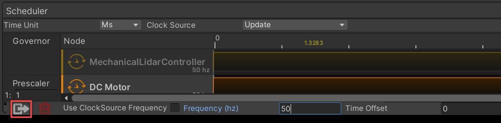
In the Scheduler panel, double-click the MechanicalLidarController node.
- In the Scheduler bar, change the Frequency (Hz) to
50. - Select the exit icon to close the Scheduler bar.
Hover over the DC Motor node and use the arrows to place it before MechanicalLidarController.
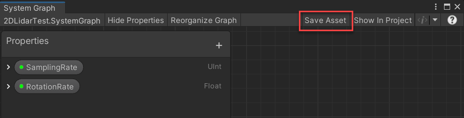
In the System Graph window, select Save Asset to save your changes.
Create the sensor
After you have completed the setup of the system graph for your 2D sensor, you can now create the sensor for the scene.
To create the sensor:
- In the Hierarchy window, right-click and select Create Empty.
- Name the GameObject 2D Lidar.
- Right-click the 2D Lidar GameObject and select 3D Object > Capsule to create a child GameObject.
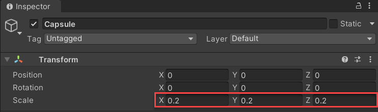
Select the Capsule GameObject and in the Transform component, set the Scale to
0.2for X, Y, and Z.Note
If the scale is not set correctly, the sensor will scan the interior of the capsule.
Configure the sensor
- Select the 2D Lidar GameObject.
- With it selected, click Add Component in the Inspector window, then select System Graph Component.
- In the System Graph Component, select System Graph Asset and attach the 2DLidarTest system graph.
- Select the Capsule GameObject.
Select Add Component, then select Camera Sensing Component.
Note
The Camera Sensing Component must be set on the moving part of the Lidar. In this tutorial, this is the Capsule GameObject.
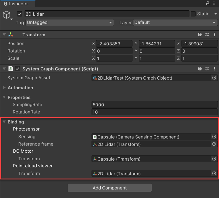
Bind the system graph components
In the System Graph Component of the 2D Lidar GameObject, under Bindings, do the following:
- Bind the 2D Lidar GameObject to the following:
- Photosensor > Reference frame
- Point cloud viewer > Transform
- Bind the Capsule GameObject to the following:
- Photosensor > Sensing
- DC Motor > Transform
Test your sensor
After completing the above steps, your sensor should now be ready to test. Create some GameObjects around the 2D Lidar for the sensor to hit.
The following steps will help to verify all components are working on your 2D Lidar:
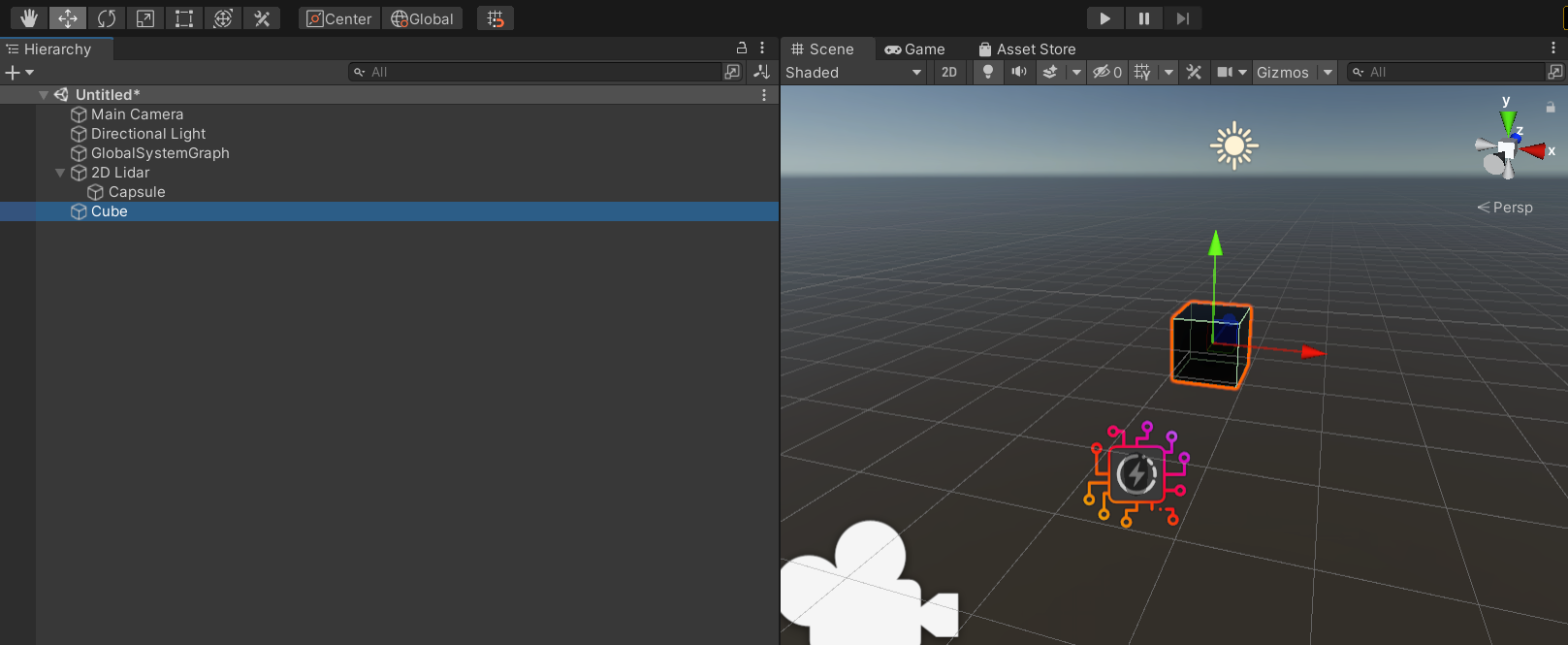
- In the Hierarchy window, right-click and select 3D Object > Cube.
Select the following GameObjects, and change the Position in the Transform component to the following:
GameObject X axis Y axis Z axis Cube 0.25 0 -2.5 2D Lidar 0.5 0.15 -6.5 Main Camera 0 0.7 -8 Enter Play mode.
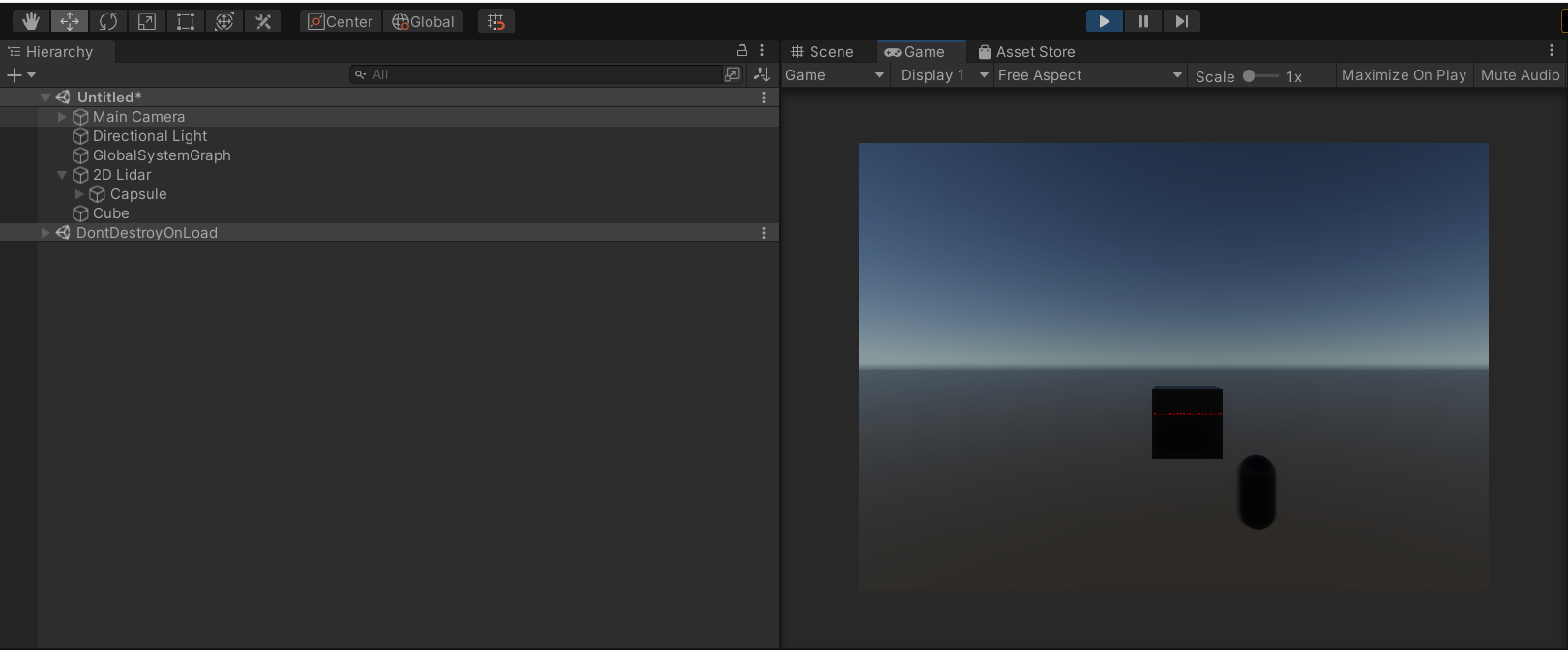
If the setup is correct, the Game view should look like this:
You can also validate the sensor in the Scene view. Select the Scene view window, then select the Capsule GameObject. The Scene view should be similar to the image below:
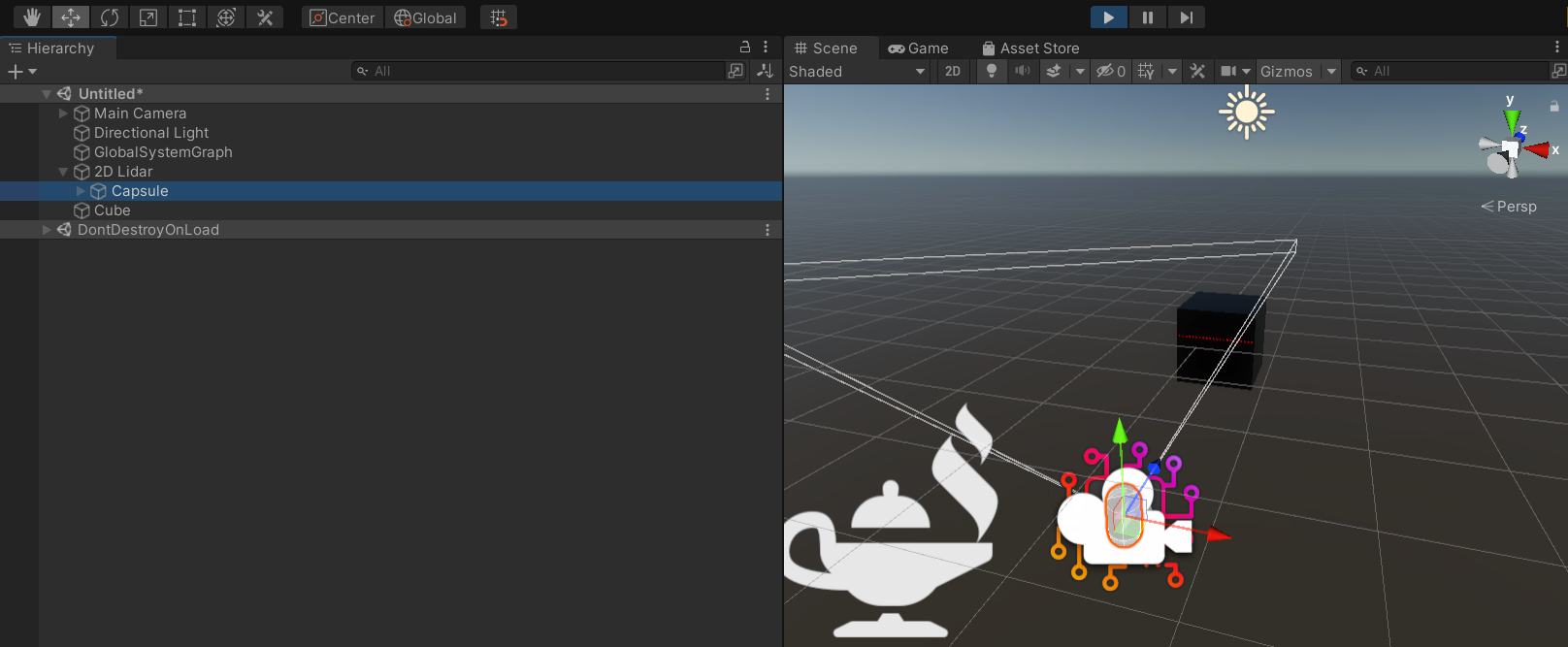
If the point cloud is visible and there is constant movement on the Y axis of the Rotation transform, then the simulation is working.
Congratulations on your first custom sensor emulation on Unity SensorSDK!