CAD vs meshes
CAD models that have been created with CAD software aren't tessellated. Examples of CAD software are CATIA, NX, SolidWorks, Alias, and STEP. CAD models contain exact parametric geometries.
This table summarizes the main differences between CAD data and mesh data:
| Information type | CAD data | Mesh data |
|---|---|---|
| Illustration | 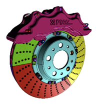 |
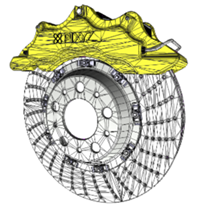 |
| Geometry | Boundary representation (BREP), which contain patches, faces, boundaries | Meshes, which comprise polygon edges, vertices |
| Data type | Parametric exact geometries | Dead data |
| Hierarchy | Design product structure | Simplified tree |
| Metadata | Product manufacturing information (PMI), properties, etc. | No metadata |
| Textures | Surface colors Materials: physical properties, textures |
Materials: visualization UVs |
CAD geometries are also referred to as, among others:
- Boundary representation (B-rep or BREP)
- Non-uniform rational basis spline (NURBS)
- Constructive solid geometry (CSG)
CAD bodies and CAD surfaces are made up of CAD faces, which are delimited by boundaries. CAD faces are also referred to as CAD patches.
To display CAD faces in a 3D application, you must create tessellated meshes, that is, polygonal models, from CAD geometries.
A mesh is a model that's made up of multiple contiguous polygons. Polygons are usually quadrangles that equal two coplanar triangles. These polygons make up discretized geometries. Mesh geometries can be read by a GPU and rendered in a 3D application.
CAD models may contain additional engineering and design information, such as metadata and product manufacturing information (PMI). You can target data preparation based on this information.
Using digital content creation software (DCC), you can natively create tessellated meshes. Examples of DCC software are Maya, 3DS Max, Blender, and Modo. For example, you can export meshes as .fbx files. Then, you can reimport the exported files into Unity 3D using Asset Transformer Toolkit.
Meshes may contain, among others, these attributes:
- Normals, which you can use to define how meshes react to light
- UVs are texture coordinates that you can use to display textures on meshes
You can keep this information or recreate it.
To optimize meshes, you can create levels of details (LODs) by applying efficient and conservative decimation.