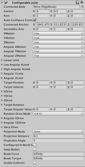
Configurable Joint
Switch to ScriptingConfigurable Joints are extremely customizable. They expose all joint-related properties of PhysX, so they are capable of creating behaviors similar to all other joint types.
Details
There are two primary functions that the Configurable Joint can perform: movement/rotation restriction and movement/rotation acceleration. These functions depend on a number of inter-dependent properties. It may require some experimentation to create the exact behavior you’re trying to achieve. We’ll now give you an overview of the Joint’s functionality to make your experimentation as simple as possible.
Movement/Rotation Restriction
You specify restriction per axis and per motion type. XMotion, YMotion, and ZMotion allow you to define translation along that axis. Angular XMotion, Angular YMotion, and Angular ZMotion allow you to define rotation around that axis. Each one of these properties can be set to Free (unrestricted), Limited (restricted based on limits you can define), or Locked (restricted to zero movement).
Limiting Motion
When you have any of the “Motion” properties set to Limited, you can define the limitations of movement for that axis. You do this by changing the values of one of the “Limit” properties.
For translation of movement (non-angular), the Linear Limit property will define the maximum distance the object can move from its origin. Translation on any “Motion” properties set to Limited will be restricted according to Linear Limit->Limit. Think of this Limit property as setting a border around the axis for the object.
Bouncyness, Spring, and Damper will define the behavior of the object when it reaches the Limit on any of the Limited “Motion” axes. If all of these values are set to 0, the object will instantly stop moving when it reaches the border. Bouncyness will make the object bounce back away from the border. Spring and Damper will use springing forces to pull the object back to the border. This will soften the border, so the object will be able to pass through the border and be pulled back instead of stopping immediately.
Limiting Rotation
Limiting rotation works almost the same as limiting motion. The difference is that the three “Angular Motion” properties all correspond to different “Angular Limit” properties. Translation restriction along all 3 axes are defined by the Linear Limit property, and rotation restriction along each of the 3 axes is defined by a separate “Angular Limit” property per axis.
Angular XMotion limitation is the most robust, as you can define a Low Angular XLimit and a High Angular XLimit. Therefore if you want to define a low rotation limit of –35 degrees and a high rotation limit of 180 degrees, you can do this. For the Y and Z axes, the low and high rotation limits will be identical, set together by the Limit property of Angular YLimit or Angular ZLimit.
The same rules about object behavior at the rotation limits from the Limiting Motion section applies here.
Movement/Rotation Acceleration
You specify object movement or rotation in terms of moving the object toward a particular position/rotation, or velocity/angular velocity. This system works by defining the “Target” value you want to move toward, and using a “Drive” to provide acceleration which will move the object toward that target. Each “Drive” has a Mode, which you use to define which “Target” the object is moving toward.
Translation Acceleration
The XDrive, YDrive, and ZDrive properties are what start the object moving along that axis. Each Drive’s Mode will define whether the object should be moving toward the Target Position or Target Velocity or both. For example, when XDrive’s mode is set to Position, then the object will try to move to the value of Target Position->X.
When a Drive is using Position in its Mode, its Position Spring value will define how the object is moved toward the Target Position. Similarly, when a Drive is using Velocity in its Mode, its Maximum Force value will define how the object is accelerated to the Target Velocity.
Rotation Acceleration
Rotation acceleration properties: Angular XDrive, Angular YZDrive, and Slerp Drive function the same way as the translation Drives. There is one substantial difference. Slerp Drive behaves differently from the Angular Drive functionality. Therefore you can choose to use either both Angular Drives or Slerp Drive by choosing one from the Rotation Drive Mode. You cannot use both at once.
Properties
| Property: | Function: |
|---|---|
| Anchor | The point where the center of the joint is defined. All physics-based simulation will use this point as the center in calculations |
| Axis | The local axis that will define the object’s natural rotation based on physics simulation |
| Secondary Axis | Together, Axis and Secondary Axis define the local coordinate system of the joint. The third axis is set to be orthogonal to the other two. |
| XMotion | Allow movement along the X axis to be Free, completely Locked, or Limited according to Linear Limit |
| YMotion | Allow movement along the Y axis to be Free, completely Locked, or Limited according to Linear Limit |
| ZMotion | Allow movement along the Z axis to be Free, completely Locked, or Limited according to Linear Limit |
| Angular XMotion | Allow rotation around the X axis to be Free, completely Locked, or Limited according to Low and High Angular XLimit |
| Angular YMotion | Allow rotation around the Y axis to be Free, completely Locked, or Limited according to Angular YLimit |
| Angular ZMotion | Allow rotation around the Z axis to be Free, completely Locked, or Limited according to Angular ZLimit |
| Linear Limit | Boundary defining movement restriction, based on distance from the joint’s origin |
| Limit | The distance in units from the origin to the wall of the boundary |
| Bouncyness | Amount of bounce-back force applied to the object when it reaches the Limit |
| Spring | Strength of force applied to move the object back to the Limit. Any value other than 0 will implicitly soften the boundary |
| Damper | Resistance strength against the Spring |
| Low Angular XLimit | Boundary defining lower rotation restriction, based on delta from original rotation |
| Limit | The rotation in degrees that the object’s rotation should not drop below |
| Bouncyness | Amount of bounce-back torque applied to the object when its rotation reaches the Limit |
| Spring | Strength of force applied to move the object back to the Limit. Any value other than 0 will implicitly soften the boundary |
| Damper | Resistance strength against the Spring |
| High Angular XLimit | Boundary defining upper rotation restriction, based on delta from original rotation. |
| Limit | The rotation in degrees that the object’s rotation should not exceed |
| Bouncyness | Amount of bounce-back torque applied to the object when its rotation reaches the Limit |
| Spring | Strength of force applied to move the object back to the Limit. Any value other than 0 will implicitly soften the boundary |
| Damper | Resistance strength against the Spring |
| Angular YLimit | Boundary defining rotation restriction, based on delta from original rotation |
| Limit | The rotation in degrees that the object’s rotation should not exceed |
| Bouncyness | Amount of bounce-back torque applied to the object when its rotation reaches the Limit |
| Spring | Strength of torque applied to move the object back to the Limit. Any value other than 0 will implicitly soften the boundary |
| Damper | Resistance strength against the Spring |
| Angular ZLimit | Boundary defining rotation restriction, based on delta from original rotation |
| Limit | The rotation in degrees that the object’s rotation should not exceed |
| Bouncyness | Amount of bounce-back torque applied to the object when its rotation reaches the Limit |
| Spring | Strength of force applied to move the object back to the Limit. Any value other than 0 will implicitly soften the boundary |
| Damper | Resistance strength against the Spring |
| Target Position | The desired position that the joint should move into |
| Target Velocity | The desired velocity that the joint should move along |
| XDrive | Definition of how the joint’s movement will behave along its local X axis |
| Mode | Set the following properties to be dependent on Target Position, Target Velocity, or both |
| Position Spring | Strength of a rubber-band pull toward the defined direction. Only used if Mode includes Position |
| Position Damper | Resistance strength against the Position Spring. Only used if Mode includes Position |
| Maximum Force | Amount of strength applied to push the object toward the defined direction. Only used if Mode includes Velocity |
| YDrive | Definition of how the joint’s movement will behave along its local Y axis |
| Mode | Set the following properties to be dependent on Target Position, Target Velocity, or both |
| Position Spring | Strength of a rubber-band pull toward the defined direction. Only used if Mode includes Position. |
| Position Damper | Resistance strength against the Position Spring. Only used if Mode includes Position. |
| Maximum Force | Amount of strength applied to push the object toward the defined direction. Only used if Mode includes Velocity. |
| ZDrive | Definition of how the joint’s movement will behave along its local Z axis |
| Mode | Set the following properties to be dependent on Target Position, Target Velocity, or both. |
| Position Spring | Strength of a rubber-band pull toward the defined direction. Only used if Mode includes Position |
| Position Damper | Resistance strength against the Position Spring. Only used if Mode includes Position |
| Maximum Force | Amount of strength applied to push the object toward the defined direction. Only used if Mode includes Velocity |
| Target Rotation | This is a Quaternion. It defines the desired rotation that the joint should rotate into |
| Target Angular Velocity | This is a Vector3. It defines the desired angular velocity that the joint should rotate into |
| Rotation Drive Mode | Control the object’s rotation with either X & YZ or Slerp Drive by itself |
| Angular XDrive | Definition of how the joint’s rotation will behave around its local X axis. Only used if Rotation Drive Mode is Swing & Twist |
| Mode | Set the following properties to be dependent on Target Rotation, Target Angular Velocity, or both |
| Position Spring | Strength of a rubber-band pull toward the defined direction. Only used if Mode includes Position |
| Position Damper | Resistance strength against the Position Spring. Only used if Mode includes Position |
| Maximum Force | Amount of strength applied to push the object toward the defined direction. Only used if Mode includes Velocity. |
| Angular YZDrive | Definition of how the joint’s rotation will behave around its local Y and Z axes. Only used if Rotation Drive Mode is Swing & Twist |
| Mode | Set the following properties to be dependent on Target Rotation, Target Angular Velocity, or both |
| Position Spring | Strength of a rubber-band pull toward the defined direction. Only used if Mode includes Position |
| Position Damper | Resistance strength against the Position Spring. Only used if Mode includes Position |
| Maximum Force | Amount of strength applied to push the object toward the defined direction. Only used if Mode includes Velocity |
| Slerp Drive | Definition of how the joint’s rotation will behave around all local axes. Only used if Rotation Drive Mode is Slerp Only |
| Mode | Set the following properties to be dependent on Target Rotation, Target Angular Velocity, or both |
| Position Spring | Strength of a rubber-band pull toward the defined direction. Only used if Mode includes Position |
| Position Damper | Resistance strength against the Position Spring. Only used if Mode includes Position |
| Maximum Force | Amount of strength applied to push the object toward the defined direction. Only used if Mode includes Velocity |
| Projection Mode | Properties to track to snap the object back to its constrained position when it drifts off too much |
| Projection Distance | Distance from the Connected Body that must be exceeded before the object snaps back to an acceptable position |
| Projection Angle | Difference in angle from the Connected Body that must be exceeded before the object snaps back to an acceptable position |
| Congfigure in World Space | If enabled, all Target values will be calculated in World Space instead of the object’s Local Space |
| Break Force | Applied Force values above this number will cause the joint to be destroyed |
| Break Torque | Applied Torque values above this number will cause the joint to be destroyed |
| Enable Collision | When checked, this enables collisions between bodies connected with a joint. |